
Process for Production of High-Purity Diaryl Carbonate

a diaryl carbonate, high-purity technology, applied in the direction of carbonic/haloformic acid esters purification/separation, separation processes, sustainable manufacturing/processing, etc., can solve the problem of reducing the yield of aromatic carbonate, unable to use as raw material for the production of aromatic polycarbonate, and unable to achieve economic effect of carrying out the method, etc. problem, to achieve the effect of stably producing

Active Publication Date: 2007-11-22
ASAHI KASEI KK
View PDF11 Cites 24 Cited by
  • Summary
  • Abstract
  • Description
  • Claims
  • Application Information

AI Technical Summary

Benefits of technology

[0038] By implementing the present invention, a high-purity diaryl carbonate having low contents of intermediate boiling point and high boiling point impurities as required for producing a high-quality and high-performance polycarbonate can be produced stably for a prolonged period of time using as a starting material a reaction mixture containing an alkyl aryl carbonate obtained through a transesterification reaction between a dialkyl carbonate and an aromatic monohydroxy compound.

Problems solved by technology

However, this process has the problem of using phosgene, and in addition chlorinated impurities that are difficult to separate out are present in the aromatic carbonate produced using this process, and hence this aromatic carbonate cannot be used as a raw material for the production of the aromatic polycarbonate.
To make the aromatic carbonate capable of using as a raw material of a transesterification method polycarbonate, a troublesome multi-stage separation / purification processes such as enough washing with a dilute aqueous alkaline solution and hot water, oil / water separation, distillation and so on are thus required.
Furthermore, the yield of aromatic carbonate decreases due to hydrolysis loss and distillation loss during this separation / purification processes.
Therefore, there are many problems in carrying out this method economically on an industrial scale.
The equilibrium is biased extremely toward the original system and the reaction rate is slow, and hence there are many difficulties in producing aromatic carbonates industrially using this method.
Of these, a continuous stirring tank reactor (CSTR) system in which a distillation column is provided on the top of the reactor has been proposed as the continuous system, but there are problems such as the reaction rate being slow, and a gas-liquid interface in the reactor being small, based on the volume of the liquid.
Hence it is not possible to make the conversion high.
However, it has been shown that various problems remain with such diaryl carbonate separation / purification methods using these distillations.
More specifically, the purity of the diphenyl carbonate obtained through the above 1) is low, and moreover this is a batch process and hence is not suitable for mass production on an industrial scale.
With the method of the above III), since the diphenyl carbonate is heated to a high temperature at the bottom of each of two of the distillation columns, i.e. the light fraction separating column and the methyl phenyl carbonate separating column, and is then subjected to a high temperature in the diphenyl carbonate separating column, the diphenyl carbonate is altered, bringing about a decrease in the purity and a decrease in the yield, which is undesirable.
The process of IV in which the diphenyl carbonate is obtained from the bottom of the column is unsuitable since the purity is low and hence a desired polycarbonate cannot be produced.
With this process, such chlorinated impurities are not separated out sufficiently, and hence it is not be possible to use the diphenyl carbonate as a raw material for a polycarbonate.
Furthermore, in Patent Document 32, the temperature and time at which phenol starts to be distilled off in the case that reaction is carried out with bisphenol A are given as a method of evaluating the purity of the diphenyl carbonate obtained through the distillation, but this test method cannot evaluate whether the diphenyl carbonate is suitable for polymerization.
This is because even for diphenyl carbonate of low purity such that a polycarbonate of the required degree of polymerization cannot be produced, the initial reaction in which phenol is eliminated occurs sufficiently.
Moreover, since with this evaluation method, a large amount of 2.3 ppm of NaOH based on the bisphenol A is used as a catalyst, even for diphenyl carbonate containing, for example, 1 ppm of chlorinated impurities, an incorrect evaluation that the diphenyl carbonate is of high purity and is suitable as a raw material for a polycarbonate would be obtained.
In ordinary polymerization, since such a large amount of an alkaline catalyst is not used, this evaluation method is not suitable for evaluating the purity of diphenyl carbonate to be used for producing polycarbonate.
When a diaryl carbonate for which the amounts of such intermediate boiling point by-products and high boiling point by-products have not been reduced down to a sufficient level is used as the raw material of a transesterification method polycarbonate, it has been discovered that these intermediate boiling point by-products and high boiling point by-products cause discoloration and a deterioration in the properties of the polycarbonate produced.

Method used


Image

  • Process for Production of High-Purity Diaryl Carbonate
  • Process for Production of High-Purity Diaryl Carbonate

Examples


example 1

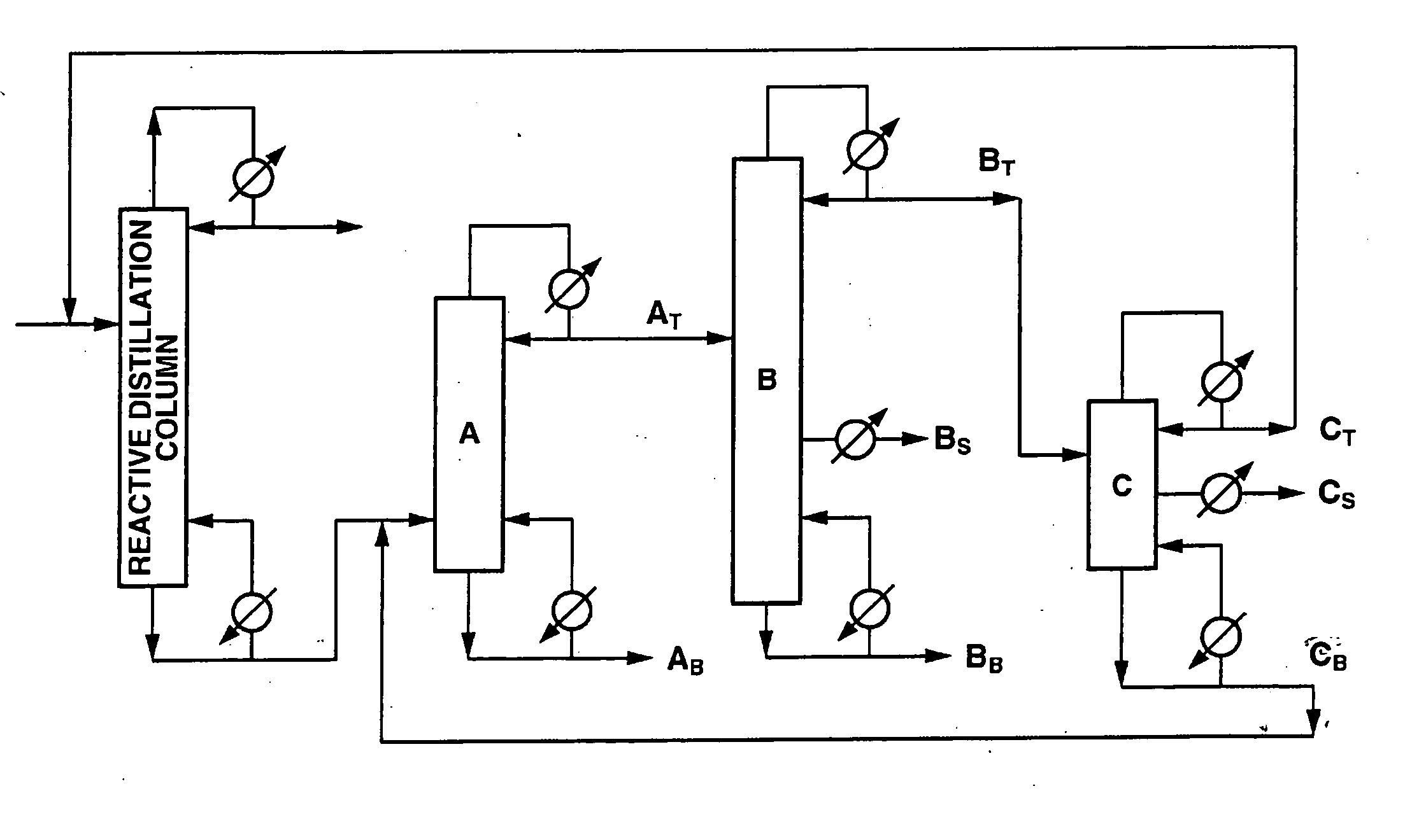
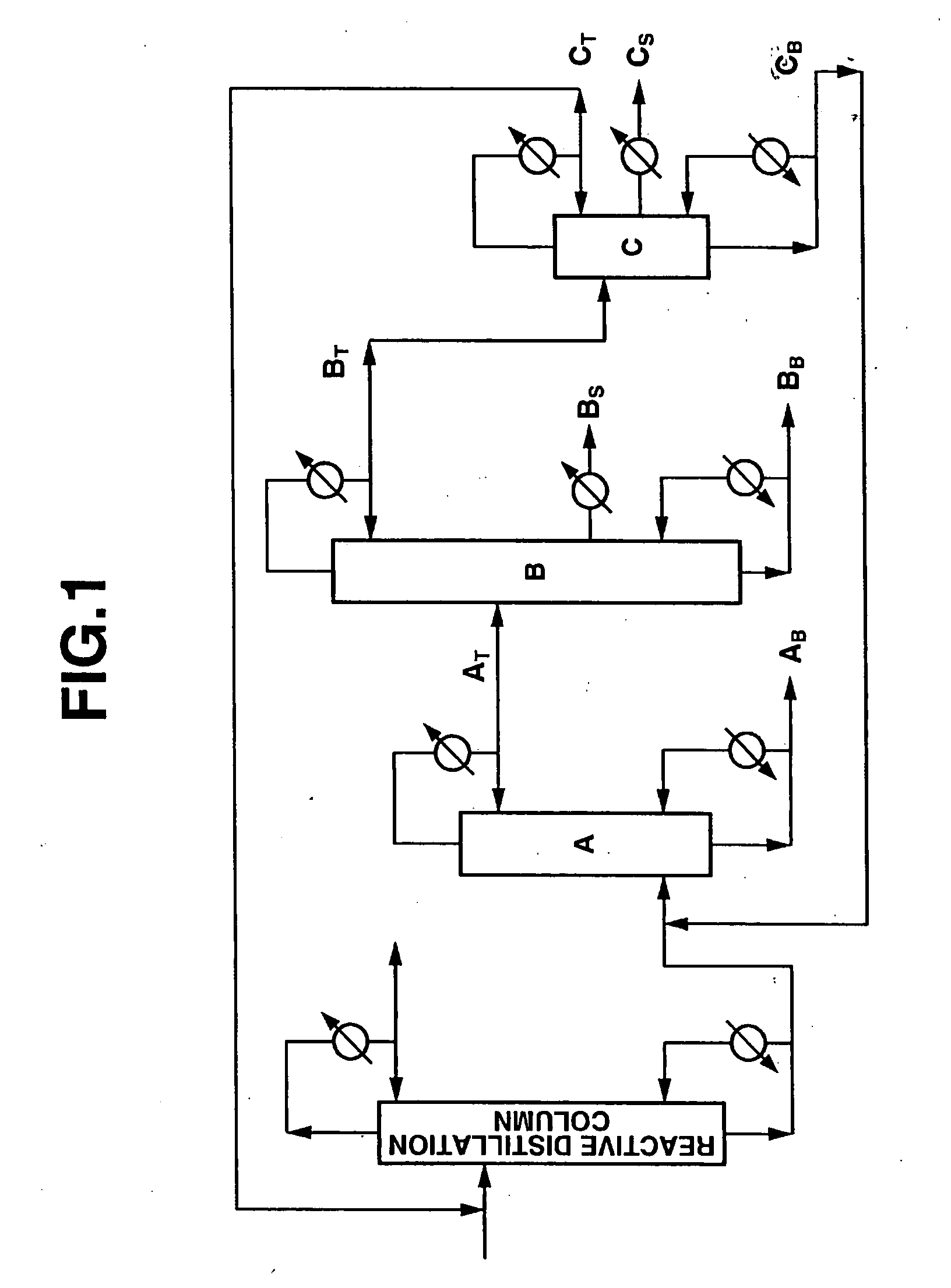
[0113] Diphenyl carbonate was produced using an apparatus comprising a reactive distillation column (height: 6 m, diameter: 10 inches, internal: sieve tray, number of stages: 20), a high boiling point material separating column A (height: 5 m, diameter: 6 inches, internal: Dixon packing, theoretical number of stages: 25), a diaryl carbonate purifying column B (height: 8 m, diameter: 6 inches, internal: sieve tray, number of stages: 30) and an intermediate boiling point material separating column C (height: 4 m, diameter: 2 inches, internal: Dixon packing, theoretical number of stages: 15) as shown in FIG. 1.

[0114] A reaction mixture containing 18.7% by weight of methyl phenyl carbonate that had been obtained by subjecting phenol and dimethyl carbonate containing anisole to a transesterification reaction was used as a starting material. This starting material contained 27.5% by weight of dimethyl carbonate, 8.2% by weight of anisole, 43.9% by weight of phenol, 1.5% by weight of diph...

example 2

[0123] Reactive distillation and separation / purification by distillation were carried out using the same process as in Example 1, except that the conditions for the separation / purification by distillation were changed to a column bottom temperature of 210° C., a column top pressure of 3800 Pa, and a reflux ratio of 0.61 for the high boiling point material separating column A, a column bottom temperature of 220° C., a column top pressure of 6700 Pa, and a reflux ratio of 1.5 for the diaryl carbonate purifying column B, and a column bottom temperature of 200° C., a column top pressure of 2400 Pa, and a reflux ratio of 0.35 for the intermediate boiling point material separating column C. The purity of the diphenyl carbonate after 500 hours and 1000 hours was at least 99.999% by weight, and each of intermediate boiling point by-products and high boiling point by-products was undetectable, the content thereof being not more than 1 ppm. Moreover, the halogen content of the diphenyl carbon...

example 3

[0124] Using the diphenyl carbonate obtained in Example 1, an aromatic polycarbonate was produced using the process described in example 1 in International Publication No. 99 / 64492. The obtained aromatic polycarbonate having the number average molecular weight of 10500 was injection molded at 310° C. into a test piece (3.2 mm thickness). This test piece had b* value of 3.2 (this value indicating a yellowness in accordance with a CIELAB method) and no yellow tinge, and was uncolored, which was excellent in transparency. After crushing these test pieces by a crushing machine, injection molding of the crushed pieces at 310° C. was repeated five times, whereupon the b* value of the test piece thus obtained was 3.5, and hence marked discoloration was not observed. Moreover, a heat resistance ageing test (120° C., 500 hours) was carried out on the test piece (b* value=3.2) produced by injection molding the above aromatic polycarbonate, whereupon the b* value was 3.5, and hence marked disc...


PUM

PropertyMeasurementUnit
Temperatureaaaaaaaaaa
Fractionaaaaaaaaaa

Abstract

It is an object of the present invention to provide a specific industrially useful process that enables a high-purity diaryl carbonate having low contents of intermediate boiling point and high boiling point impurities as required for producing a high-quality and high-performance polycarbonate to be produced stably for a prolonged period of time using as a starting material a reaction mixture containing an alkyl aryl carbonate obtained through a transesterification reaction between a dialkyl carbonate and an aromatic monohydroxy compound. There have been various proposals regarding processes for the production of reaction mixtures containing aromatic carbonates by means of a reactive distillation method. The present inventors have now carried out studies aimed at discovering a specific process enabling a high-purity diaryl carbonate that can be used as a raw material of a high-quality and high-performance polycarbonate to be continuously produced stably for a prolonged period of time from such a reaction mixture. As a result, the present inventors have reached to the present invention after discovering that the above object can be attained through a process in which separation by distillation is carried out using three distillation columns in a specified order. Moreover, the present inventors have discovered that it is particularly preferable if a reactive distillation column and the three distillation columns, each of which has a specified structure, and the three distillation columns are each operated under specified distillation conditions.

Description

TECHNICAL FIELD[0001] The present invention relates to an industrial process for the production of a high-purity diaryl carbonate. More particularly, the present invention relates to a process for the production of a high-purity diaryl carbonate, which is useful as a raw material of a transesterification method polycarbonate, by taking a reaction mixture containing an alkyl aryl carbonate that has been obtained through a transesterification reaction between a dialkyl carbonate and an aromatic monohydroxy compound as a starting material, and carrying out a transesterification reaction using a reactive distillation column, and then subjecting a reaction mixture containing a diaryl carbonate thus obtained to separation and purification using three continuous multi-stage distillation columns. BACKGROUND ART [0002] A high-purity diphenyl carbonate is important as a raw material for the production of an aromatic polycarbonate, which is the most widely used engineering plastics, without us...

Claims


Application Information

Patent Timeline
IPC IPC(8): C07C69/96
CPCB01D3/009B01D3/146C07C68/06C07C68/08C08G64/307C07C69/96Y02P20/582Y02P20/10B01D3/16B01D3/22
Inventor FUKUOKA, SHINSUKEMIYAJI, HIRONORIHACHIYA, HIROSHIMATSUZAKI, KAZUHIKO
Owner ASAHI KASEI KK
Learn More