Eureka AIR delivers breakthrough ideas for toughest innovation challenges, trusted by R&D personnel around the world.

Method Of Wirebonding That Utilizes A Gas Flow Within A Capillary From Which A Wire Is Played Out

a gas flow and capillary technology, applied in the direction of printed circuit structure association, printed circuit assembling, printed element electric connection formation, etc., can solve the problems of mechanical stress, inherent limitations of each of the aforementioned techniques, and achieve the effect of improving the severing of the bond wir

Inactive Publication Date: 2007-10-04
FORMFACTOR INC
View PDF99 Cites 52 Cited by
  • Summary
  • Abstract
  • Description
  • Claims
  • Application Information

AI Technical Summary

Benefits of technology

[0047] It is a general object of the present invention to provide improved techniques for interconnecting electronic components, especially microelectronic components.
[0048] It is another object of the present invention to provide improved techniques for mounting contact structures to electronic components, especially semiconductor dies.
[0049] It is another object of the present invention to provide improved techniques for fabricating resilient contact structures.
[0050] It is another object of the present invention to provide improved techniques for making electronic assemblies.
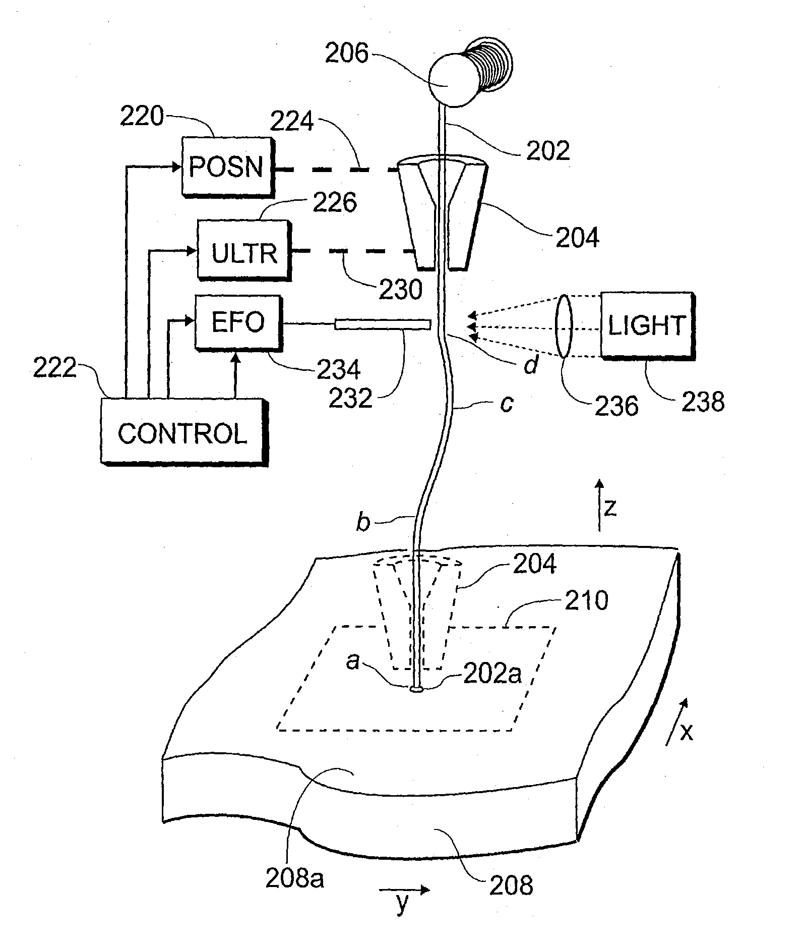
[0051] It is another object of the present invention to provide improved techniques for making wire bond connections to electronic components, including improvements in severing bond wires.
[0067] According to an aspect of the invention, the rigidity (stability) of a “conventional” wire bond (such as a bond wire extending between a bond pad on a semiconductor die and a leadframe finger) can be improved by overcoating the bond wire with a superstructure. This is important, for example, in avoiding shorting adjacent wires during transfer molding of a package body.

Problems solved by technology

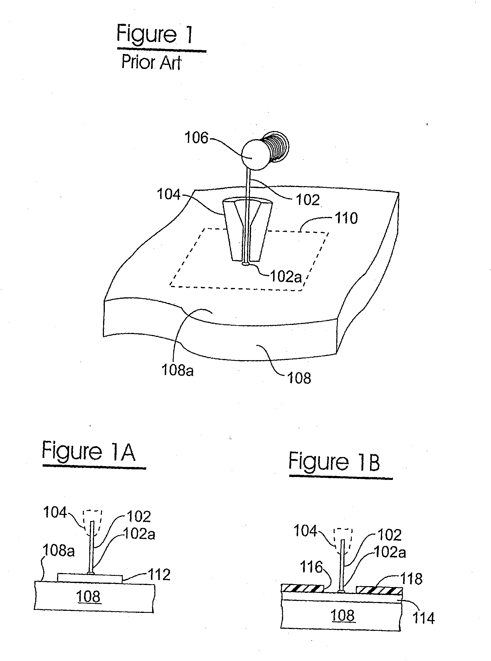
This patent is cited as exemplary of the fact that wire-bonding has been known for decades, and also of the fact that it is generally undesirable to “deform” the wire while moving the capillary.
Preferably, such a “hermetic” coating would not be conductive, as it would tend to short out the device (die).
Surface mount technology solves certain problems associated with making interconnections between electronic components, but has proven itself not to be the panacea it was once envisioned to be.
The challenges to effecting reliable surface mount include forming solder bumps with controlled geometry and high aspect ratio (ration of height to width), sometimes referred to as “solder columns”.
The manufacture of such test fixtures is a specialty requiring a different test fixture for each array pattern, and is consequently both expensive and time-consuming.
The difference in thermal coefficients of expansion between the die and surrounding elements (e.g., package, board, electrical connections) results in mechanical stress.
Moreover, each of the aforementioned techniques suffers from inherent limitations.
Sockets address this concern, but add (often unacceptable) cost to the overall system.
Moreover, socketing tends to exhibit inferior connection reliability, as contrasted with soldered connections.
Surface mount techniques, such as the aforementioned technique of providing the first electronic component with solder balls and providing the second electronic component with conductive pads require carefully controlled processes to effect reliably, and do not lend themselves well to disassembly (replacement of one of the electronic components).
For example, gold has a very low yield strength, a characteristic which makes it extremely counter-intuitive to employ a gold wire in (or as) a resilient contact structure.
In other instances, true springs, exhibiting purely elastic deformation, are not desired, as they would impose too high of a load upon the substrate whereupon they are mounted.

Method used


Image

  • Method Of Wirebonding That Utilizes A Gas Flow Within A Capillary From Which A Wire Is Played Out
  • Method Of Wirebonding That Utilizes A Gas Flow Within A Capillary From Which A Wire Is Played Out
  • Method Of Wirebonding That Utilizes A Gas Flow Within A Capillary From Which A Wire Is Played Out

Examples


case-1

[0220] CASE-1 discloses mounting the resilient contact structures to a variety of electronic components, including:

[0221] (a) ceramic and plastic semiconductor packages;

[0222] (b) laminated printed circuit boards (PCBs), Teflon™ based circuit boards, multi-layer ceramic substrates, silicon-based substrates, varieties of hybrid substrates, and other substrates for integration of electronic systems known to those skilled in the art.

[0223] (c) semiconductor devices, such as silicon and gallium arsenide devices; and

[0224] (d) passive devices, such as resistors and capacitors.

[0225] CASE-1 discloses the following wire materials and dimensions:

[0226] (a) gold, aluminum or copper, alloyed (or doped) with beryllium, cadmium, silicon or magnesium;

[0227] (b) solder, specifically lead-tin solder wire;

[0228] (c) alloys of silver and platinum; and

[0229] (d) diameters ranging between 0.0005 and 0.0050 inches.

[0230] CASE-1 discloses employing the following wirebonders and techniques:

[023...

case-2

[0278] CASE-2 discloses a number of specific uses for resilient contact structures are described, including a variety of interposer embodiments, wherein:

[0279] (a) a resilient contact structure is mounted to one side of an interposer substrate at a plated through hole, and a resilient contact structure is mounted to another, opposite side of the interposer substrate at the plated through hole;

[0280] (b) a resilient contact structure is mounted to one side of an interposer substrate at a plated through hole, and looped contact structure is mounted to another, opposite side of the interposer substrate at the plated through hole;

[0281] (c) a resilient contact structure having a portion extends from a plated through hole up from one side of the interposer substrate, and having another portion which extends through the through hole to beneath the interposer substrate;

[0282] (d) a molded plastic interposer substrate is provided with one set of holes extending into the substrate from on...

embodiment 900

[0609]FIG. 9A illustrates an embodiment 900 of the use of a sacrificial member 902 (shown in dashed lines) in conjunction with forming a resilient contact structure 930 suitable for use as a probe. In this example, the sacrificial member is suitably formed of aluminum.

[0610] A plurality (one of many shown) of depressions 904 are formed, such as by etching, engraving, stamping, or the like, in the top surface 902a of the sacrificial member 902. The bottom (as viewed) surface of the depression 904 has an irregular topography, such as in the form of inverted pyramids ending in apexes. A thin layer 906 of a conductive material, such as gold or rhodium (alternatively, tin or solder, such as when contacting solder terminals) is deposited in the depression, in any known manner. The depression 904 is then substantially filled with a conductive material 908 such as nickel, in any known manner. A layer 910 of a conductive material such as gold is then deposited over the filler material 908, i...


PUM

PropertyMeasurementUnit
Flow rateaaaaaaaaaa
Shapeaaaaaaaaaa

Abstract

Contact structures exhibiting resilience or compliance for a variety of electronic components are formed by bonding a free end of a wire to a substrate, configuring the wire into a wire stem having a springable shape, severing the wire stem, and overcoating the wire stem with at least one layer of a material chosen primarily for its structural (resiliency, compliance) characteristics. A variety of techniques for configuring, severing, and overcoating the wire stem are disclosed. In an exemplary embodiment, a free end of a wire stem is bonded to a contact area on a substrate, the wire stem is configured to have a springable shape, the wire stem is severed to be free-standing by an electrical discharge, and the free-standing wire stem is overcoated by plating. A variety of materials for the wire stem (which serves as a falsework) and for the overcoat (which serves as a superstructure over the falsework) are disclosed. Various techniques are described for mounting the contact structures to a variety of electronic components (e.g., semiconductor wafers and dies, semiconductor packages, interposers, interconnect substrates, etc.), and various process sequences are described. The resilient contact structures described herein are ideal for making a “temporary” (probe) connections to an electronic component such as a semiconductor die, for burn-in and functional testing. The self-same resilient contact structures can be used for subsequent permanent mounting of the electronic component, such as by soldering to a printed circuit board (PCB). An irregular topography can be created on or imparted to the tip of the contact structure to enhance its ability to interconnect resiliently with another electronic component. Among the numerous advantages of the present invention is the great facility with which the tips of a plurality of contact structures can be made to be coplanar with one another. Other techniques and embodiments, such as wherein the falsework wirestem protrudes beyond an end of the superstructure, or is melted down, and wherein multiple free-standing resilient contact structures can be fabricated from loops, are described.

Description

CROSS-REFERENCE TO RELATED APPLICATIONS [0001] This is a continuation-in-part of commonly-owned, copending U.S. patent application Ser. No. 08 / 340,144, filed Nov. 15, 1994 (status pending) and its counterpart PCT Patent Application No. PCT / US94 / 13373, filed Nov. 16, 1994 (status pending; collectively, the US and PCT parent cases are referred to hereinafter as “CASE-2”), both of which are continuations-in-part of commonly-owned, copending U.S. patent application Ser. No. 08 / 512,812, filed Nov. 16, 1993 (status pending; referred to hereinafter as “CASE-1”).BACKGROUND OF THE INVENTION [0002] Due to its superior conductive and non-corrosive characteristics, gold is a “material of choice” for making electrical connections between electronic components. For example, it is well known to make a plurality of wire bond connections between conductive pads on a semiconductor die and inner ends of leadframe fingers. This is cited as one example of making permanent connections between a first, “a...

Claims


Application Information

Patent Timeline
IPC IPC(8): B23K20/00C23C18/16C25D5/08C25D5/22C25D7/12C25D21/02G01R1/04G01R1/067G01R1/073G01R31/28H01L21/00H01L21/48H01L21/56H01L21/60H01L21/603H01L21/66H01L23/48H01L23/485H01L23/49H01L23/498H01L25/065H01L25/16H05K1/14H05K3/20H05K3/30H05K3/32H05K3/34H05K3/36H05K3/40H05K7/10
CPCB23K20/004B23K2201/40C25D5/08C25D5/22C25D7/12C25D21/02G01R1/0483G01R1/06711G01R1/07314G01R1/07342G01R1/07357G01R1/07378G01R31/2884G01R31/2886H01L21/4853H01L21/4889H01L21/563H01L21/6715H01L21/67248H01L21/67253H01L21/67288H01L22/20H01L23/49811H01L24/11H01L24/12H01L24/16H01L24/45H01L24/48H01L24/72H01L24/78H01L24/81H01L24/85H01L25/0652H01L25/16H01L2224/1134H01L2224/13099H01L2224/16145H01L2224/45015H01L2224/45144H01L2224/4554H01L2224/48091H01L2224/48227H01L2224/48599H01L2224/49109H01L2224/73203H01L2224/78301H01L2224/81801H01L2224/85043H01L2224/85045H01L2224/851H01L2224/85201H01L2224/85205H01L2225/0651H01L2225/06527H01L2225/06555H01L2225/06572H01L2924/01004H01L2924/01005H01L2924/01006H01L2924/01011H01L2924/01012H01L2924/01013H01L2924/01014H01L2924/01015H01L2924/01018H01L2924/01022H01L2924/01025H01L2924/01027H01L2924/01028H01L2924/01029H01L2924/0103H01L2924/01031H01L2924/01039H01L2924/01042H01L2924/01046H01L2924/01047H01L2924/01049H01L2924/0105H01L2924/01051H01L2924/01074H01L2924/01075H01L2924/01077H01L2924/01078H01L2924/01079H01L2924/01082H01L2924/01083H01L2924/01322H01L2924/014H01L2924/10329H01L2924/14H01L2924/15153H01L2924/15165H01L2924/15312H01L2924/1532H01L2924/16195H01L2924/19041H01L2924/19043H01L2924/20751H01L2924/20753H01L2924/20754H01L2924/20755H01L2924/30105H01L2924/30107H01L2924/3011H01L2924/3025H05K1/141H05K3/20H05K3/308H05K3/326H05K3/3421H05K3/3426H05K3/368H05K3/4015H05K3/4092H05K7/1069H05K2201/0397H05K2201/068H05K2201/1031H05K2201/10318H05K2201/10378H05K2201/10719H05K2201/10734H05K2201/10757H05K2201/10878H05K2201/10909H05K2201/10946H01L24/49H01R12/52H01L2924/01019H01L2924/01023H01L2924/01024H01L2924/01033H01L2924/01044H01L2924/01045H01L2924/01076H01L2224/45124H01L2224/45147H01L2924/10253H01L2924/12041H01L2924/07802Y10T29/49149H01L2924/00014H01L2924/20752H01L2924/00H01L2224/32225H01L2224/73265H01L2924/181H01L2924/12044H01L2224/85203H01L2224/81901H01L2224/73251H01L2224/8592H01L2224/49H01L2224/45H01L2224/48H01L2224/78H01L2224/85H01L2224/11H01L2224/16H01L2224/12B23K2101/40Y02P70/50C25D5/605C25D5/611H01L2924/00015H01L2924/2075H01L2924/01204H01L2924/013H01L2924/00013H01L2924/01048H01L2224/72H01L2924/00012
Inventor ELDRIDGE, BENJAMIN N.GRUBE, GARY W.KHANDROS, IGOR Y.MATHIEU, GAETAN L.
Owner FORMFACTOR INC
Why Eureka
Eureka Blog
Learn More