
Gold-containing catalyst with porous structure

a porous structure, gold-containing technology, applied in the direction of physical/chemical process catalysts, separation processes, cell components, etc., can solve the problems of large surface energy, affecting the objective of reaction, and greatly reducing catalytic activity, etc., to achieve the highest possible activity, the effect of extending the service life and avoiding the melting poin

Inactive Publication Date: 2007-09-27
UNIV OF BREMEN +1
View PDF4 Cites 18 Cited by
  • Summary
  • Abstract
  • Description
  • Claims
  • Application Information

AI Technical Summary

Benefits of technology

[0024] Within the respective possible concentration limits, additional optimization may be undertaken. What is considered optimal in each individual case may differ; accordingly, for example, optimization may have as its goal the highest possible activity, the longest possible service life, or even the least possible cost.
[0027] Any suitable process can be used for the shaping of the starting alloy, such as, pressing, stamping, rolling, bending, boring, hammering, cutting, and / or milling. Since these methods are usually not particularly expensive from a technical standpoint (for example, no vacuum chamber is required), virtually any desired size and shape of the catalyst can be produced simply and cost-effectively.
[0042] The plastic properties of the starting alloy make it possible, advantageously, that the alloy can even be shaped in a thin or very thin film, and this thin or very thin film can then be dealloyed at least partially by one of the above described processes.
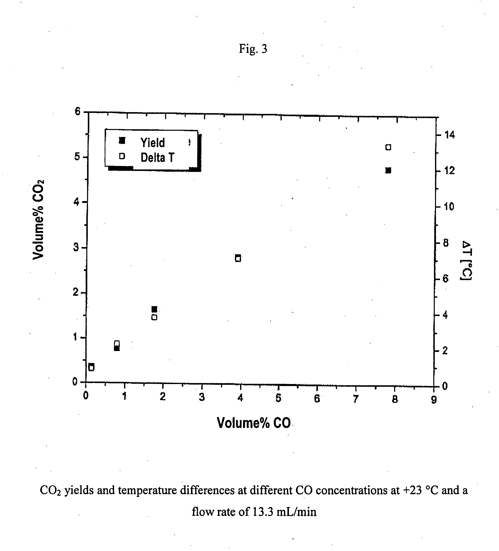
[0044] As the inventors discovered, the catalyst according to the invention has, for example, an excellent capability to oxidize carbon monoxide (CO) to carbon dioxide (CO2) and to do this at temperatures of a carbon monoxide-containing medium, for example, a gas, a gas mixture, or a liquid, as low as about −50° C. The examples described in the following concern tests in which this oxidation was successfully performed in the range from roughly −20° C., through 0° C. and room temperature (+23° C.) all the way up to +50° C. Of course, it is to be expected that this oxidation reaction is accelerated by even higher temperatures, for example, up to approximately 150° C., using the catalyst according to the invention. In particular, catalytically mediated oxidation at low temperatures seems to be especially interesting since, with it, energy and, consequently, cost can be saved.

Problems solved by technology

However, catalysts not only accelerate a chemical reaction in this manner, but they can frequently also influence the objective of the reaction.
Such very small gold particles have, however, large surface energy and, consequently, tend to coagulate quickly, as a result of which their catalytic activity is greatly reduced.
With wet chemical processes, problems related to reproducibility of the chemical / physical properties of the catalytic systems obtained are reported.
These difficulties probably are based, for example, on the fact that, among other things, it is difficult to control the size of the gold particles, that the catalysts are poisoned by ions such as, for example, chloride, that different amounts of gold “get lost” in the pores of the support material, and that, through necessary thermal secondary processing steps, the catalytic activity of the material is altered in a non-reproducible manner.
A suitable vacuum apparatus is required for the PVD process, which makes the process expensive in terms of equipment and also imposes restrictions with regard to the size and shape of the support material used.
From this brief overview of known processes for the production of gold-containing catalysts, it is clear that, in each case, multiple complex and / or expensive steps are required before obtaining a gold-containing catalyst usable in practice.

Method used


Image

  • Gold-containing catalyst with porous structure
  • Gold-containing catalyst with porous structure
  • Gold-containing catalyst with porous structure

Examples


examples

[0059] 1. Presentation of Exemplary Gold Foams

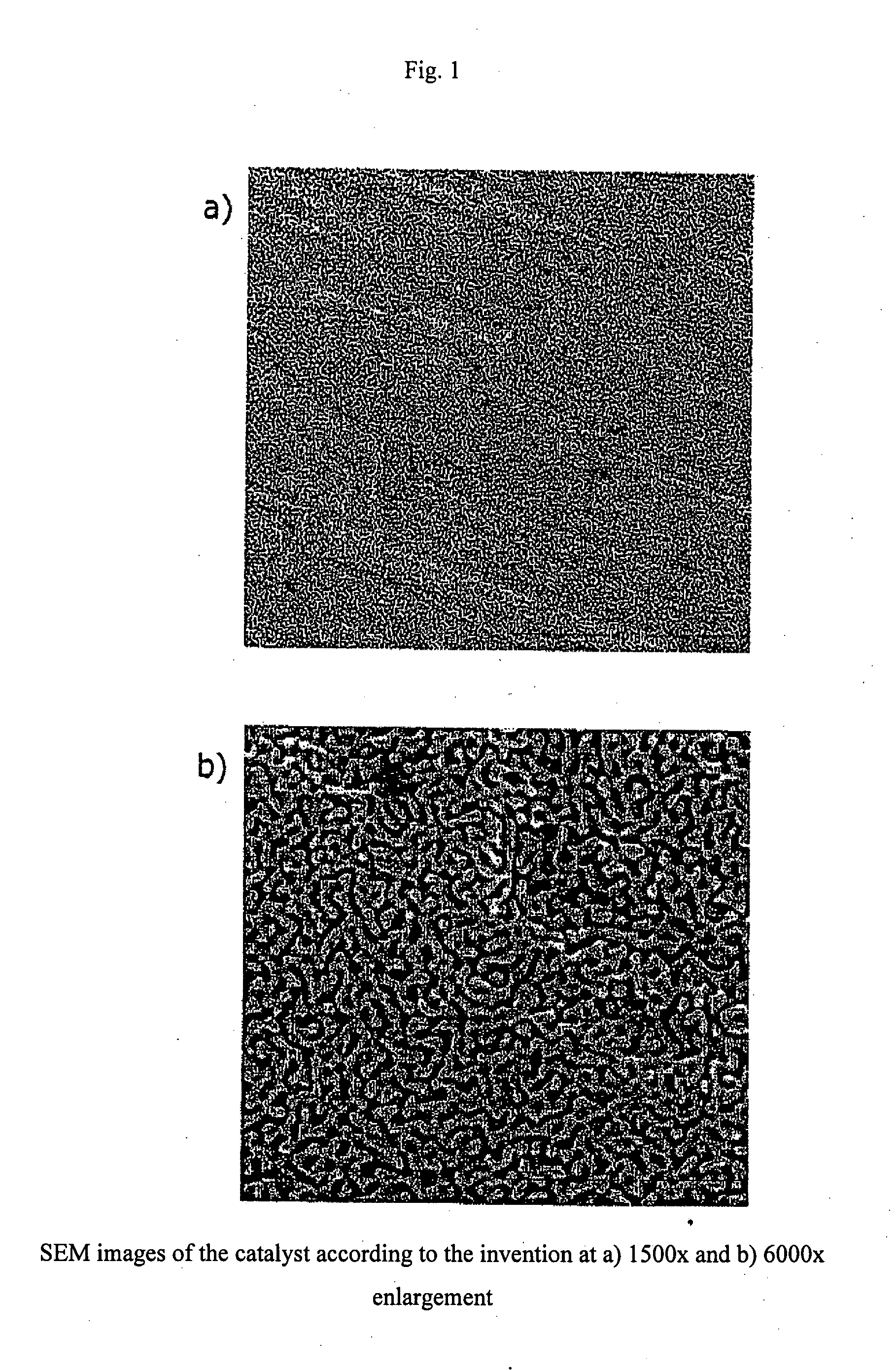
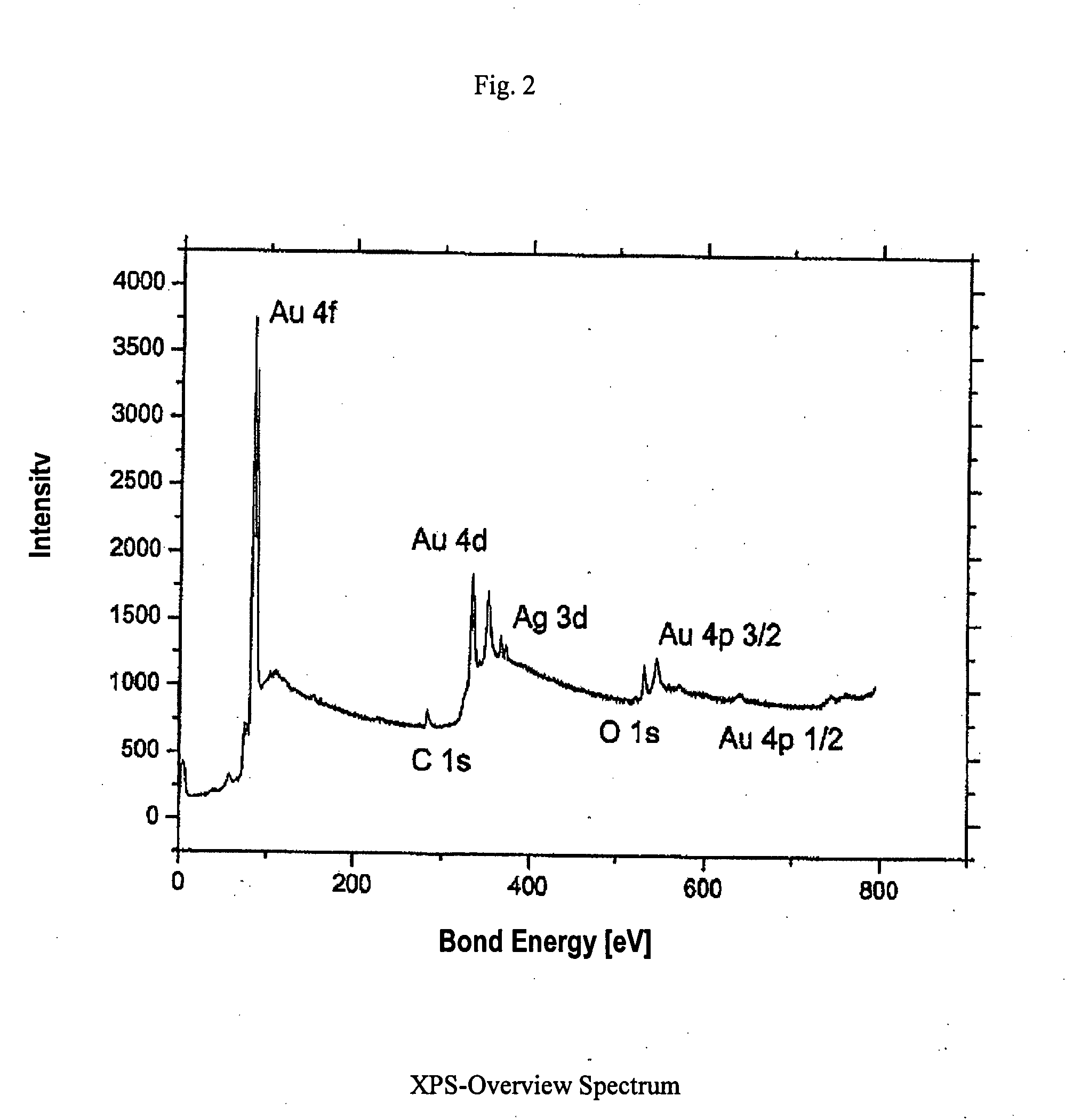
[0060] First, an Au—Ag-starting alloy with 30 atom % Au was produced. The finished starting alloy was rolled to roughly 5 mm diameter into small pieces of desired thickness. Then, the specimens were annealed for 24 hours at 850° C. For the partial dealloying and creation of the foam structure, the specimen underwent wet-chemical treatment. The wet chemical partial dealloying was carried out in a solution of 70% nitric acid. The specimens were placed on a porous glass plate in a beaker. Then, the acid was added such that the specimen was covered. Roughly 300-μm-thick specimens were dealloyed in this manner within from one to three days. The greater part of the silver portion was selectively dissolved out of the specimens by the nitric acid, and nanoporous gold foams remained. The acid was removed using a syringe and replaced with water. This was changed out several times in order to clean remaining acid residues from the specimens. The s...


PUM

PropertyMeasurementUnit
temperatureaaaaaaaaaa
diametersaaaaaaaaaa

Abstract

The invention relates to a gold-containing catalyst with porous structure that is obtainable through a process that comprises the following steps: melting together of gold and at least one less noble metal that is selected from the group consisting of silver, copper, rhodium, palladium, and platinum, and at least partial removal by dissolving the at least one less noble metal out of the starting alloy thus obtained. The catalyst has high activity and great long-term stability, despite the fact that it does not contain a support material or a compound that serves as a support material. The catalyst can be used to accelerate and / or to influence the product selectivity of oxidation and reduction reactions. The catalyst is suitable, for example, for the oxidization of carbon monoxide to carbon dioxide, which makes it usable, among other things, in a fuel cell, in particular a polymer electrolyte membrane fuel cell (PEM), for protection of the anode catalyst against blocking by carbon monoxide.

Description

[0001] The United States Government has rights in this invention pursuant to Contract No. W-7405-ENG-48 between the United States Department of Energy and the University of California for the operation of Lawrence Livermore National Laboratory.FIELD OF INVENTION [0002] The present invention relates to a gold-containing catalyst with porous structure, the use of the catalyst according to the invention to accelerate and / or influence the product selectivity of oxidation and reduction reactions, as well as a fuel cell with a catalyst according to the invention. CROSS-REFERENCE TO RELATED APPLICATIONS [0003] This application claims the benefit of German Patent Application No. XXXXXXXXXX, filed Mar. 27, 2006 and titled “GOLD-CONTAINING CATALYST WITH POROUS STRUCTURE” is incorporated herein by this reference. [0004] The action of catalysts is known to be based on the fact that they open a path to chemical reactions by which starting compounds or materials can be converted into end products...

Claims


Application Information

Patent Timeline
Patent Type & Authority Applications(United States)
IPC IPC(8): B01J23/66
CPCB01J23/52B01J23/56B01J25/00Y02E60/50H01M4/98H01M2008/1095H01M4/90
Inventor BIENER, JUERGENHAMZA, ALEX V.BAEUMER, MARCUSSCHULZ, CHRISTIANJURGENS, BIRTEBIENER, MONIKA M.
Owner UNIV OF BREMEN
Learn More