
Gas-less process and system for girth welding in high strength applications including liquefied natural gas storage tanks

a gas-less, high-strength technology, applied in the direction of welding apparatus, manufacturing tools, other domestic objects, etc., can solve the problems of adverse effects of brittleness of welds, inherent limitations of gas-less or self-shielding welding applications, and no commercial solution or method for semi-automatically, circumferentially, etc., to achieve short arc length, reduce the effect of contaminating the weld from the atmosphere and reduce the effect of contamin

Inactive Publication Date: 2007-09-27
LINCOLN GLOBAL INC
View PDF71 Cites 19 Cited by
  • Summary
  • Abstract
  • Description
  • Claims
  • Application Information

AI Technical Summary

Benefits of technology

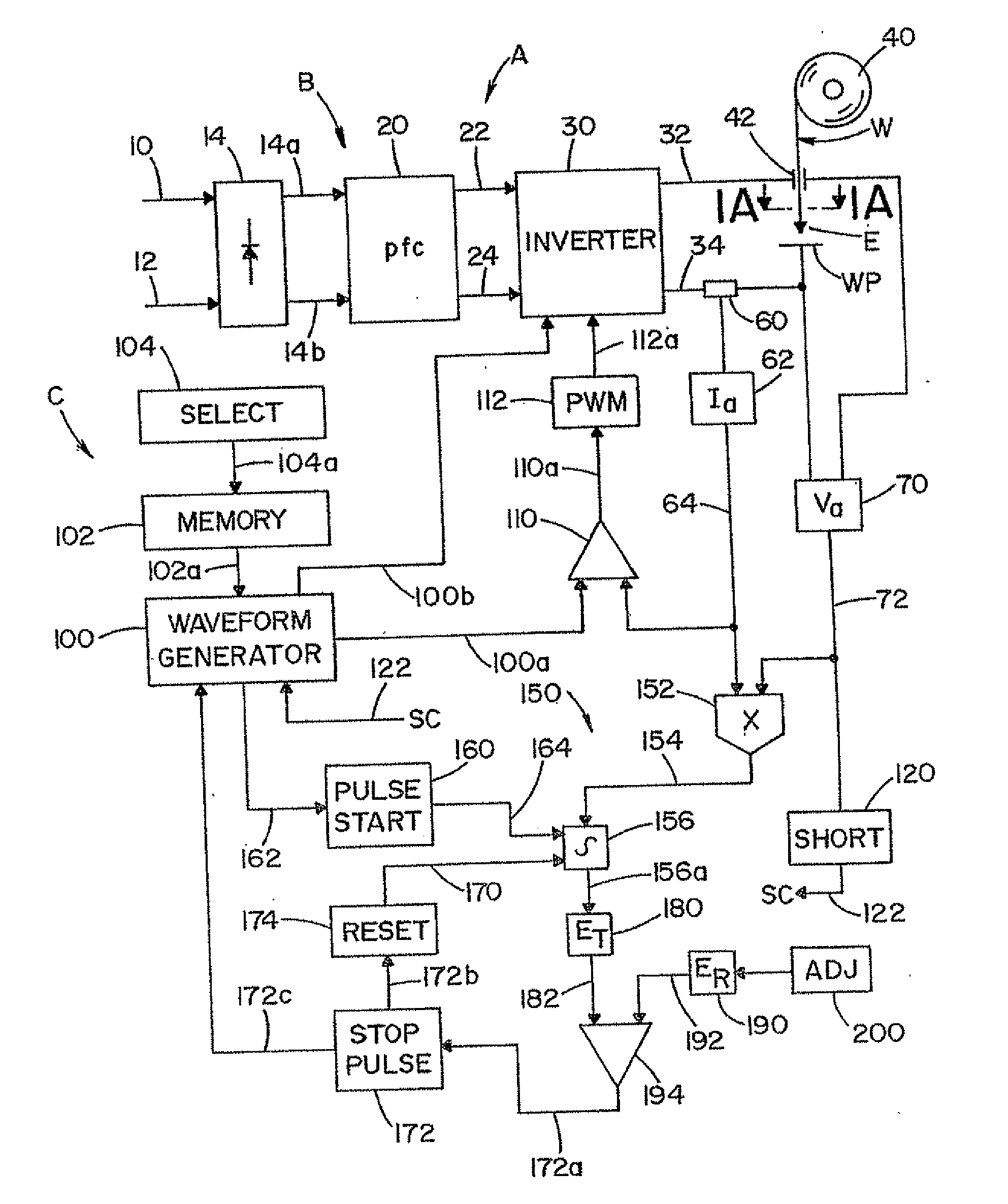
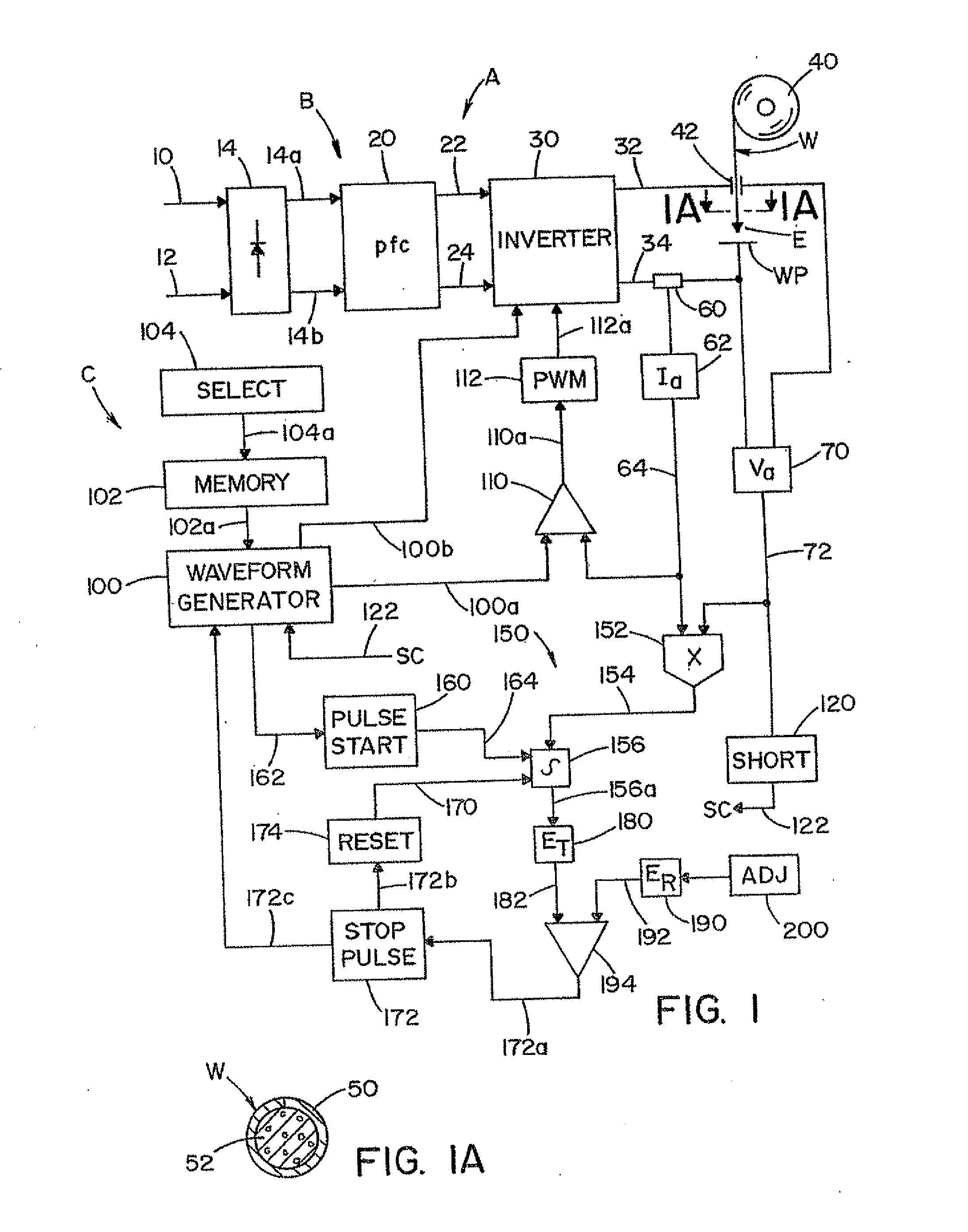
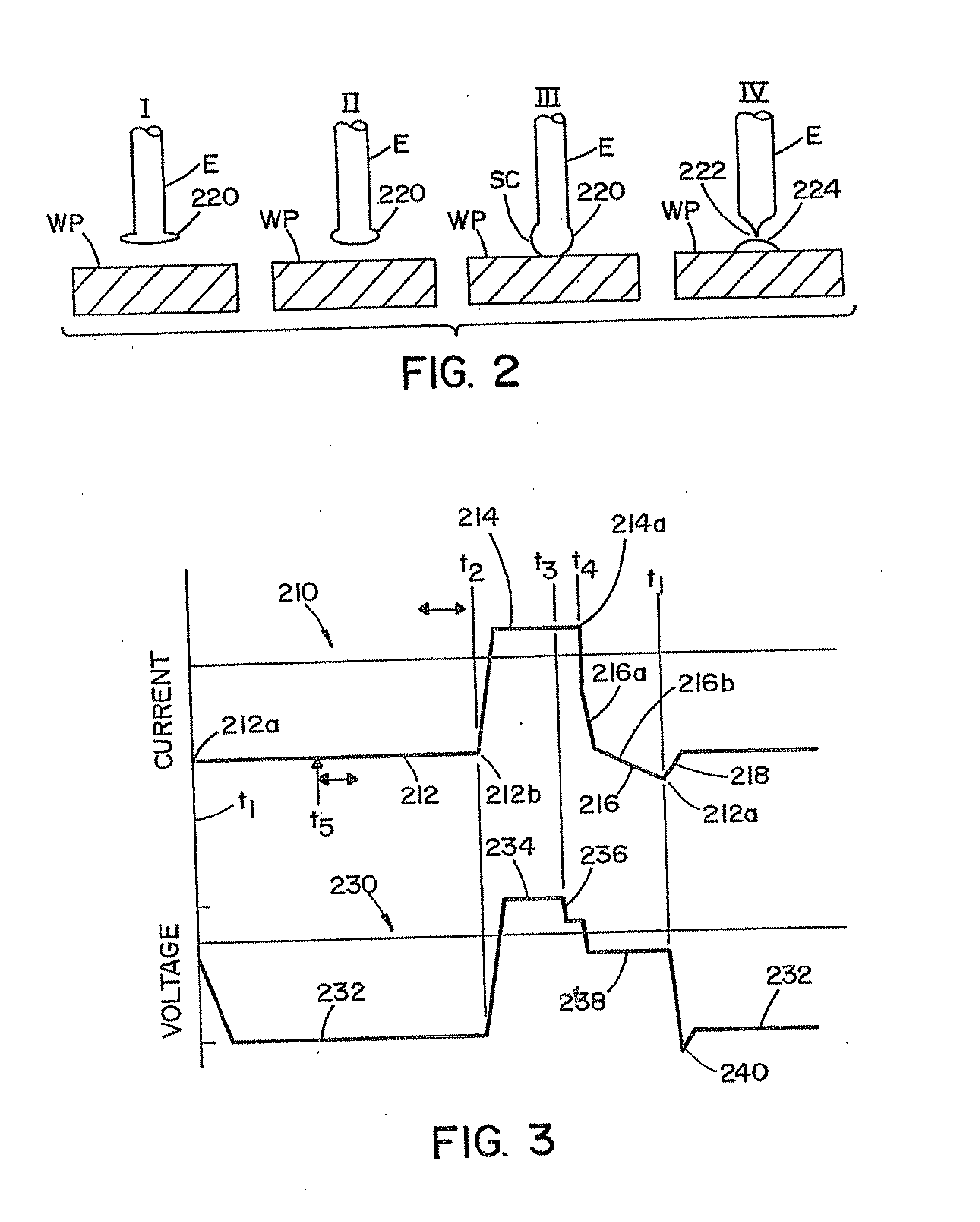
The present invention provides a system and method for welding that can create a weld that satisfies the requirements for welding American Petroleum Institute (API) Grade X-80 line pipe and LNG storage tanks. The system controls the welding arc through a specialized power source and uses a cored, self-shielded electrode to achieve the desired welding attributes. The method allows for welding in various positions and does not require additional shielding gas. The short arc welding system is an AC system and the melting pulse is controlled interactively by a feedback loop, not fixed constant values. The system can also use a flux cored electrode with alloy ingredients in the core for welding LNG storage tanks. Overall, the present invention provides a more efficient and effective solution for welding in the oil and gas industry.

Problems solved by technology

Presently, there are no commercial solutions or methods for semi-automatically, circumferentially, welding high strength pipes and pipelines with a gas-less or self-shielding welding process.
This is because the traditional technologies used for gas-less or self-shielding welding applications have inherent limitations in high strength welding applications.
However, while these chemicals, such as titanium and aluminum, make the welds stronger, they also have the adverse effects of making the welds brittle.
Further, although there exists methods for meeting these weld requirements using gas-shielded welding methods, these methods also have drawbacks which make them less than desirable.
Namely, current methods and systems for welding high strength pipes and pipelines (along with other applications) using gas-shielding methods require costly and time consuming set ups to protect the welding area from the atmosphere and elements.
This is particularly the case in pipeline applications, where the welds are often taking place outside in difficult environmental conditions.
Additionally, in the area of liquefied natural gas (LNG) storage tanks, there is presently no commercial system or method using a semi-automatic gas-less process which efficiently and effectively meets the stringent requirements needed for welding LNG storage tanks.
Because of this only certain types of welding are effective for welding LNG storage tanks, and each of the current methods have drawbacks.
However, out of the 2G position SAW can not be used effectively.
For out-of-position welding, shielded metal arc welding (SMAW) has been used, but SMAW requires a very high skill level and results in a high number of defects in welding, resulting in costly and time consuming re-welds.
Additionally, because SMAW uses a “stick electrodes” continuity in the weld can be compromised.
However, because each of these methods use gas shielding, these options are undesirable in outdoor or hostile environments and are a costly and inefficient option.

Method used


Image

  • Gas-less process and system for girth welding in high strength applications including liquefied natural gas storage tanks
  • Gas-less process and system for girth welding in high strength applications including liquefied natural gas storage tanks
  • Gas-less process and system for girth welding in high strength applications including liquefied natural gas storage tanks

Examples


example

[0101] The following discussion is directed to an example of the present invention. The present invention is not limited to the embodiment and results discussed below, but the following discussion is provided to demonstrate the results achievable from an exemplary embodiment of the present invention.

[0102] A series of test welds were made using an embodiment of the present invention, in which a self-shielded, flux cored electrode was used in a short arc welding process. In some tests a 0.062 inch diameter Lincoln Innershield NR-233 was used. The welds were made at a constant wire feed speed and travel speed. The welds were bead on plate welds, having three passes side-by-side, then two passes side-by-side in a second layer on top of the first three passes. The plate surfaces were shot blasted prior to welding to remove scale and dirt. The weld metal layer in the second layer was analyzed for nitrogen content. Because no nitrogen was intentionally incorporated in the electrodes used...


PUM

PropertyMeasurementUnit
Charpy V-Notch toughnessaaaaaaaaaa
tensile strengthaaaaaaaaaa

Abstract

A welding system and method is disclosed for girth welding high strength materials, including liquefied natural gas storage tanks, using a short arc welding process and a self-shielding electrode. The welding system contains a welding apparatus which advances the self-shielding electrode towards a workpiece to be welded and controls the arc length and the operation of the apparatus so that the weld satisfies the requirements for welding at least American Petroleum Institute Grade X-80 line pipe, or can weld liquefied natural gas storage tanks. The system additionally contains a power source with a controller for creating a current pulse introducing energy into the electrode to melt the end of the self-shielding electrode and a low current quiescent metal transfer section following the end of the melting pulse during which the melted electrode short circuits against the workpiece.

Description

PRIORITY [0001] The present application is a continuation in part of U.S. application Ser. No. 11 / 382,084, filed May 8, 2006, the entire disclosure of which is incorporated herein by reference, which is a continuation-in-part of U.S. application Ser. No. 10 / 834,141, filed Apr. 29, 2004; a continuation-in-part of U.S., application Ser. No. 10 / 959,587, filed Oct. 6, 2004; a continuation-in-part of U.S. application Ser. No. 11 / 263,064, filed Oct. 31, 2005; and a continuation-in-part of U.S. application Ser. No. 11 / 336,506, filed Jan. 20, 2006, the entire disclosures of which are also incorporated herein by reference.FIELD OF THE INVENTION [0002] The present invention relates to the art of electric arc welding and more particularly to an improved short arc welding system to be used in welding liquefied natural gas (“LNG”) storage tanks, methods of welding LNG storage tanks with self-shielded flux cored arc welding (FCAW-S) electrodes, and the composition of the electrodes. BACKGROUND [0...

Claims


Application Information

Patent Timeline
Patent Type & Authority Applications(United States)
IPC IPC(8): B23K9/00
CPCB23K9/0008B23K9/092B23K2201/12B23K35/0261B23K35/0266B23K9/23B23K2101/12
Inventor NARAYANAN, BADRISOLTIS, PATRICK T.MYERS, RUSSELL K.STEWART, ERIC
Owner LINCOLN GLOBAL INC
Learn More