
Radiation window with coated silicon support structure

a technology of support structure and xray window, which is applied in the direction of material analysis using wave/particle radiation, instruments, nuclear engineering, etc., can solve the problems of spectral contamination, difficult to achieve good spectral resolution, and many support structures that interfere with radiation passage, so as to minimize spectral contamination, reduce collimation, and maximize radiation transmission

Inactive Publication Date: 2010-05-04
MOXTEK INC
View PDF30 Cites 47 Cited by
  • Summary
  • Abstract
  • Description
  • Claims
  • Application Information

AI Technical Summary

Benefits of technology

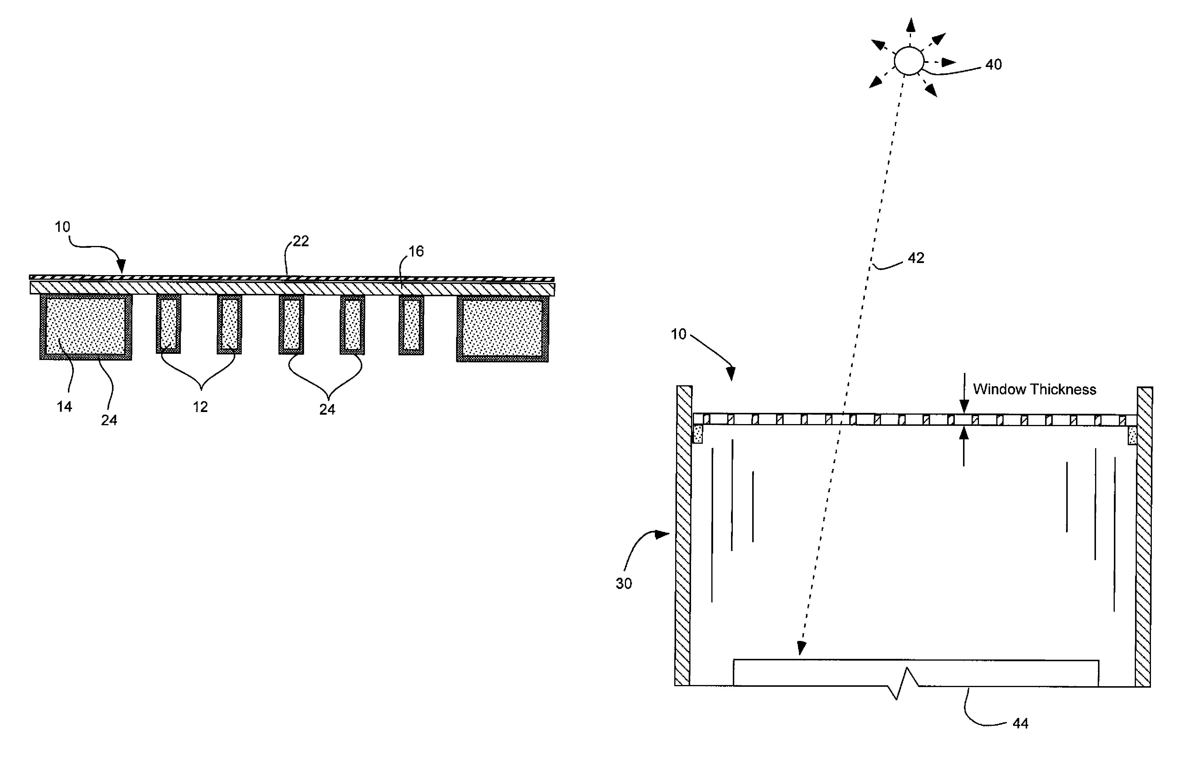
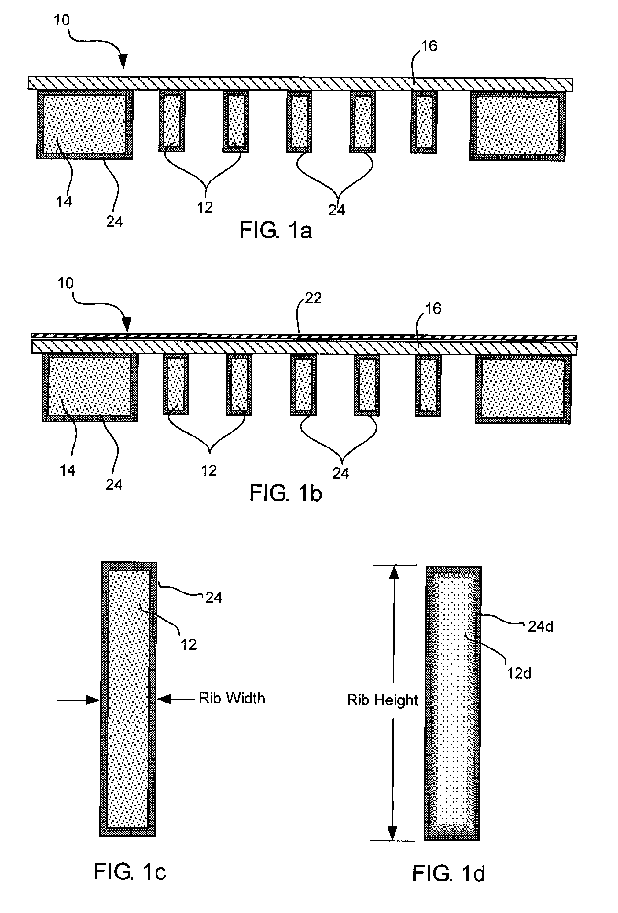
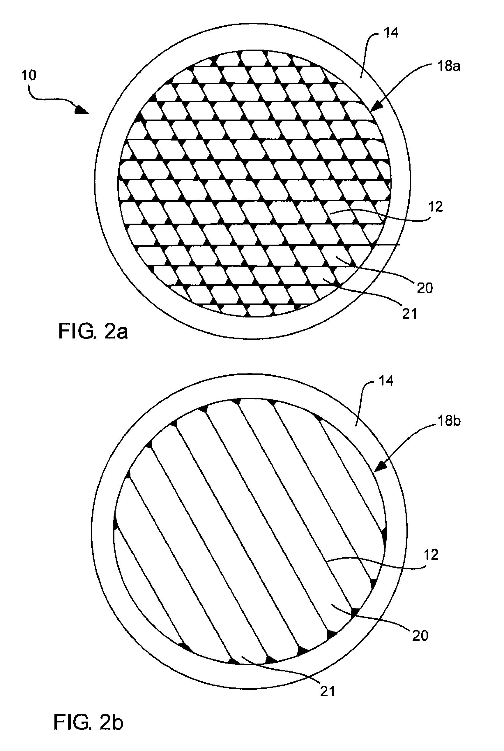
[0017]It has been recognized that it would be advantageous to develop a radiation-window with a support structure that maximizes radiation transmission; is sufficiently robust to withstand gravity, vibration, normal wear and tear, and differential pressure; minimizes spectral contamination; reduces collimation; and makes use of manufacturing processes and materials that provide suitable production yields. It has been recognized that it would be advantageous to strengthen the brittle silicon support frame without using higher atomic-mass elements. It has been recognized that it is possible to further strengthen the silicon structure by introducing low atomic-mass elements or compounds as surface coatings, and diffusing the coatings into the silicon structure to create stronger silicon-based compounds or alloys. The present invention provides a high-strength window for a radiation-detection system. A window for a radiation-detection system includes a plurality of ribs carried by a frame having an aperture therein. The ribs are made of silicon. A coating substantially envelopes each of the plurality of silicon ribs, A thin film covers the aperture and is carried by the plurality of silicon ribs and configured to pass radiation therethrough.

Problems solved by technology

The radiation detection system's design constraints define the radiation window's performance requirements.
While useful for providing support to an often thin and fragile sheet of material, many support structures can interfere with the passage of radiation through the window assembly due to the structure's composition, geometry, thickness, and / or height.
Higher atomic-mass elements used in the radiation window's sheet material and support structure composition often cause spectral contamination when used in X-ray spectrometry or fluorescence-type applications.
Good spectral resolution is more difficult to achieve when measuring a specimen comprised of lower atomic-number elements.
If absorbed, the energy is not received by the radiation-detector sensor and thus not counted by the pulse processor and multi-channel analyzer, creating an erroneous composition calculation.
The result is the confounding of the specimen's spectral energy into unknown or other elements' spectral-emission lines, called ‘stray lines.’ This tertiary fluorescence mixes with and contaminates the specimen's emission signal causing the detector to erroneously calculate the sample's elemental composition.
However, silicon is a brittle and relatively weak material for use as a structural support member.
The radiation window is a comparatively inexpensive part of the radiation detector assembly but the radiation window's failure may result in catastrophic damage and require total replacement of the radiation detector.
Support ribs spaced too far apart or grid density that is too low may cause unacceptable window-film deflection when the window must withstand a pressure differential.

Method used


Image

  • Radiation window with coated silicon support structure
  • Radiation window with coated silicon support structure
  • Radiation window with coated silicon support structure

Examples


Embodiment Construction

[0028]Reference will now be made to the exemplary embodiments illustrated in the drawings, and specific language will be used herein to describe the same. It will nevertheless be understood that no limitation of the scope of the invention is thereby intended. Alterations and further modifications of the inventive features illustrated herein, and additional applications of the principles of the inventions as illustrated herein, which would occur to one skilled in the relevant art and having possession of this disclosure, are to be considered within the scope of the invention.

[0029]The present invention provides embodiments of a high strength window for a radiation detection system, an associated radiation detection system, and an associated method of manufacturing a high strength grid for a window in a radiation detection system. In accordance with these embodiments, various details are provided herein which are applicable to all three of the window, system and manufacturing method.

[...


PUM


Abstract

A window for a radiation detection system includes a frame with an aperture therein configured to receive radiation therethrough. A plurality of silicon ribs span the aperture and are carried by the frame. A coating substantially envelopes each of the plurality of silicon ribs. A thin film covers the aperture and is carried by the plurality of silicon ribs and is configured to pass radiation therethrough.

Description

PRIORITY CLAIM[0001]This is a continuation-in-part of U.S. patent application Ser. No. 11 / 756,946, filed Jun. 1, 2007; which is herein incorporated by reference.RELATED APPLICATIONS[0002]The present application is related to copending U.S. patent application Ser. No. 11 / 756,962, filed Jun. 1, 2007; which is herein incorporated by reference.BACKGROUND[0003]1. Field of the Invention[0004]The present invention relates generally to X-ray windows with coated silicon or silicon-compound support structures.[0005]2. Related Art[0006]Radiation windows are used in radiation-detection systems, which in turn are used in detecting and sensing emitted radiation in connection with electron microscopy, X-ray telescopy, and X-ray spectroscopy. Radiation-detection systems typically include in their structure a radiation window, which can pass radiation emitted from the radiation source to a radiation detector or sensor. The radiation detection system's design constraints define the radiation window's...

Claims


Application Information

Patent Timeline
Patent Type & Authority Patents(United States)
IPC IPC(8): H01J37/252
CPCG21K1/00H01J5/18H01J37/244H01J2237/28H01J2237/164H01J2237/2445
Inventor DECKER, KEITH W.LINES, MIKEXU, DEGAOPERKINS, RAYMOND
Owner MOXTEK INC
Learn More