Light Source Module and Area Light Source Device

a technology of light source module and which is applied in the direction of static indicating device, lighting and heating apparatus, instruments, etc., can solve the problems of insufficient product requirements for users, high cost, stock risk, etc., and achieve the effect of reducing the stock amount reducing the product type of surface light source device, and reducing the stock spa

Inactive Publication Date: 2007-09-20
ORMON CORP
View PDF2 Cites 8 Cited by
  • Summary
  • Abstract
  • Description
  • Claims
  • Application Information

AI Technical Summary

Benefits of technology

[0015] In the light source module in the present invention, the light emitting element and the wiring member of the flexible print board, etc. are separated. In the light source module having the light emitting element, the wiring member can be connected later by the connector. Accordingly, a product kind of the light source module can be reduced by separating the wiring member having various shapes in accordance with uses. Therefore, a stock amount of the light source module can be reduced, and a stock space can be reduced and a stock risk can be also reduced. Further, a user of a surface light source device can personally supply the wiring member and can connect the wiring member to the light source module. Accordingly, an obtaining period of the surface light source device can be shortened. In particular, a forwarding period of a new product can be hastened in the case of development of the new product.
[0031] In still another embodiment mode of the surface light source device of the present invention, the light guide plate has a pattern for emitting light from the light emitting face by reflecting light internally guided, and the pattern is arranged on a concentric circle with a certain point as a center. If such a pattern is used, the brightness of light emitted from the light emitting face can be raised and utilization efficiency of light can be improved even in the case of a so-called point light source for locally locating the light emitting element in a narrow area.

Problems solved by technology

In a method for preparing various kinds of surface light source devices as in the former case, cost is high since a scale of its manufacturing line, a stock space, a stock risk, etc. are increased.
Further, a problem exists in that no product required in the user is necessarily found even when various kinds of surface light source devices are lined up.
Further, in a case for taking the order receiving production system as in the latter case, on the user side, a problem exists in that manufacturing lead time from ordering to delivery of the product is lengthened and product formation is delayed.
Therefore, a forwarding period of the product in the user is delayed.

Method used


Image

  • Light Source Module and Area Light Source Device
  • Light Source Module and Area Light Source Device
  • Light Source Module and Area Light Source Device

Examples


embodiment 1

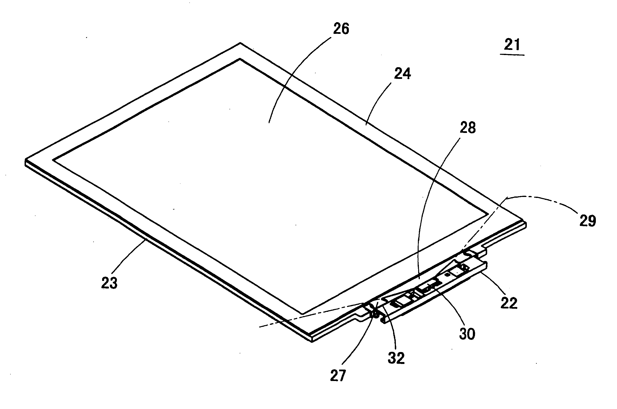
[0081]FIG. 3 is a perspective view showing a surface light source device 21 in accordance with one embodiment of the present invention. FIG. 4 is its exploded perspective view. This surface light source device 21 is constructed by a light source module 22, a light guide plate 23, a rim sheet 24, etc. The light guide plate 23 is formed by a transparent resin material of a high refractive index such as polymethyl methacrylate, polycarbonate resin, etc. A pattern 23A for reflecting light guided within the light guide plate 23 and emitting this light from an upper face (light emitting face) is formed on a lower face of the light guide plate 23. In the pattern, many fine irregularities formed in the shape of a triangular prism are arranged on the lower face of the light guide plate 23. Each pattern is arranged on a concentric circle with a light emitting point of the light source module 22 as about a center. Pattern density is small in an area near the light source module 22. Pattern den...

embodiment 2

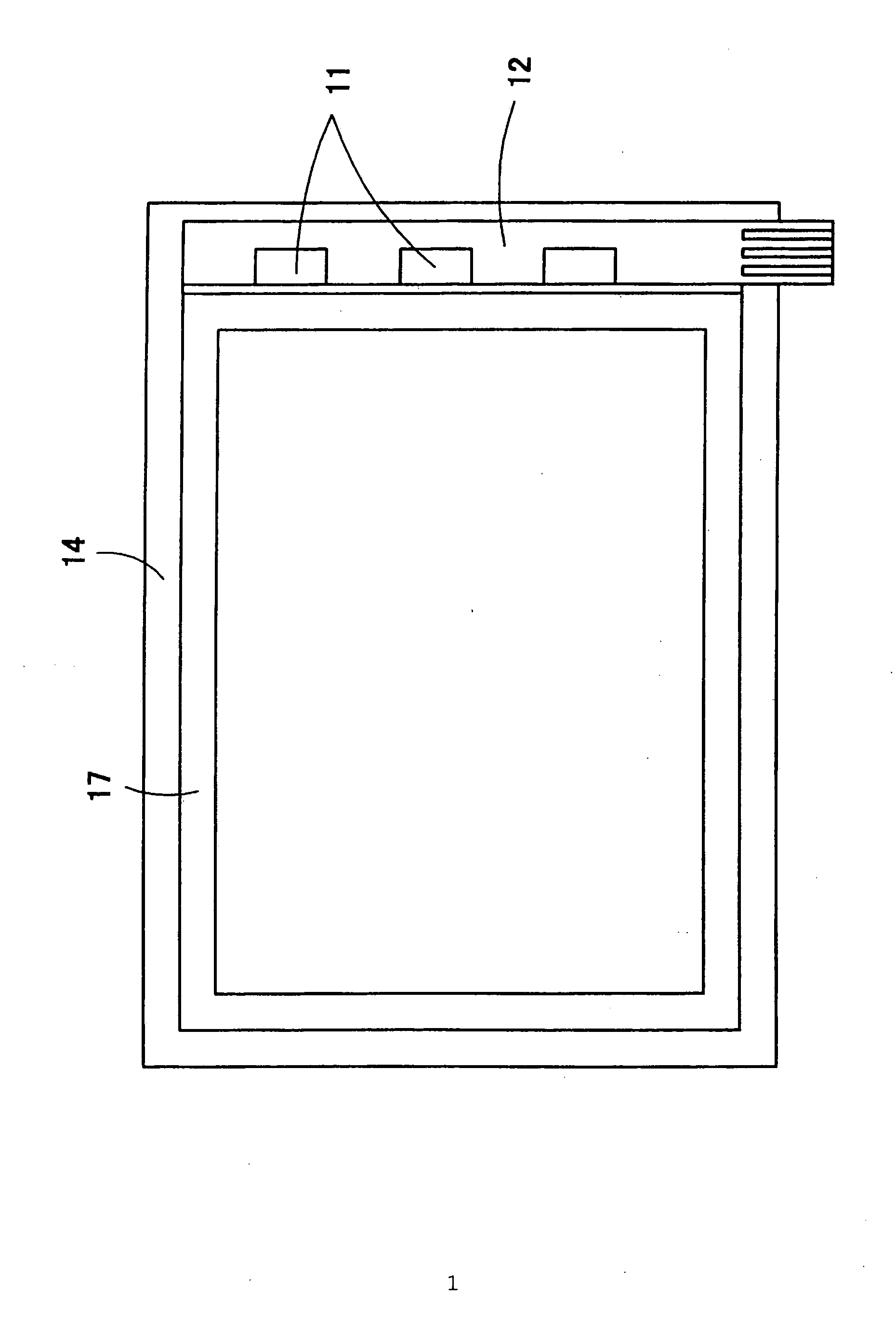
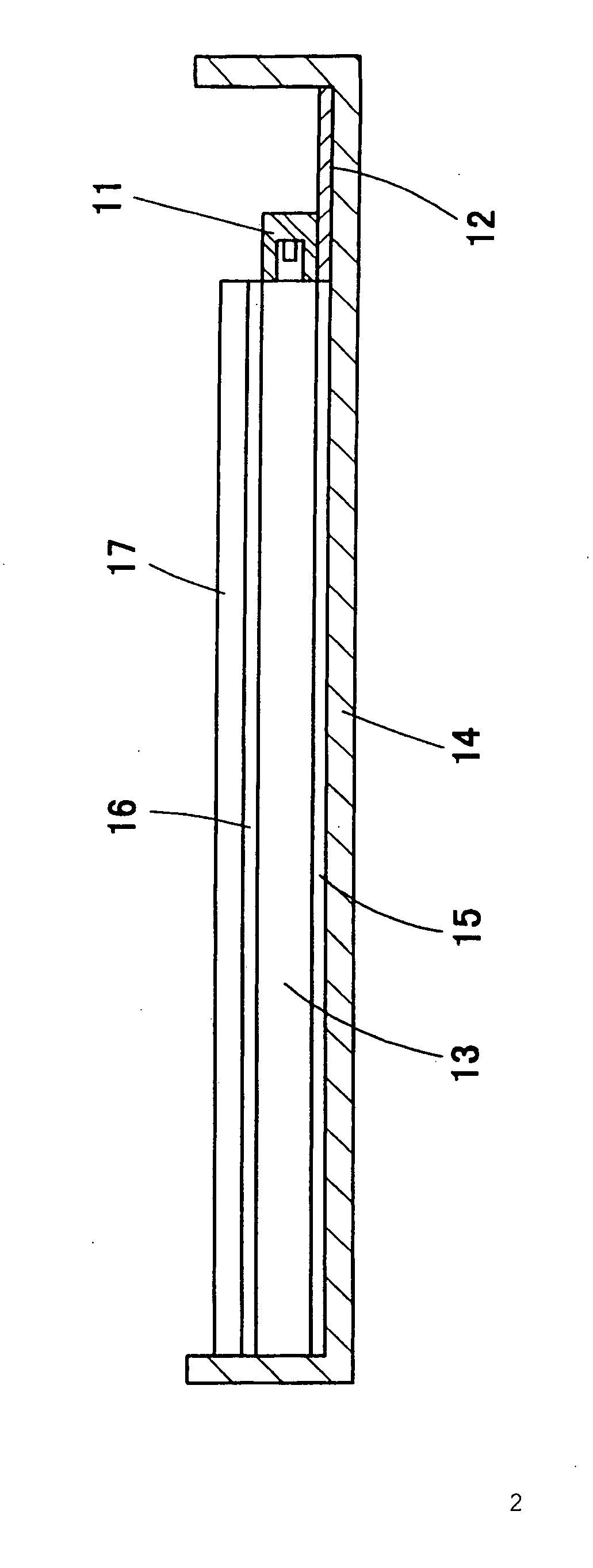
[0110]FIG. 23 is a plan view showing a surface light source device 21 in accordance with another embodiment of the present invention. FIG. 24 is a view for enlarging one portion of FIG. 23. FIGS. 25(a) and 25(b) are a plan view and a front view showing the vicinity of a light incident portion 28 of the light guide plate 23. FIGS. 25(c) and 25(d) are a rear view and a plan view of the light source module 22. In the surface light source device 21 shown in this embodiment, the light source module 22 is arranged near a corner of the light guide plate 23, and light is incident in a diagonal direction of the light guide plate 23 from the light emitting part 30.

[0111] As shown in FIGS. 25(a) and 25(b), the light incident portion 28 formed in a trapezoidal shape is arranged near a corner of the light guide plate 23, and a connected portion 27 is adjacent to the light incident portion 28 and is projected on one side of this light incident portion 28. A hole 74 for connection is bored on the...

embodiment 3

[0114]FIG. 26(a) is a schematic plan view showing the internal structure of a light source module 22 in accordance with still another embodiment of the present invention. FIG. 26(b) is a schematic sectional view of this light source module 22. In this embodiment, the light emitting part 30 is insert-molded into the light source module 22.

[0115] A connector 39 is arranged in one end portion of contact parts 34A, and a light emitting part mounting portion 40A is perpendicularly raised in the other end portion. A contact 76 is arranged at a tip of the light emitting part mounting portion 40A. Similarly, a connector 39 is arranged in one end portion of contact parts 34B, and a light emitting part mounting portion 40B is perpendicularly raised in the other end portion. A contact 76 is arranged at a tip of the light emitting part mounting portion 40B. The connector 39 of the contact parts 34A and the connector 39 of the contact parts 34B are arranged in parallel within the substrate inse...


PUM

PropertyMeasurementUnit
distanceaaaaaaaaaa
thicknessaaaaaaaaaa
thicknessaaaaaaaaaa

Abstract

A light source module (22) is provided with a light-emitting component (30) including a light-emitting diode. A light guide plate (23) for expanding a light beam from the light source module (22) into a planar shape and emitting the light beam from a light exit surface is attached to the light source module (22). For the attachment, a connection portion (32) for connecting a connected portion (27) of the light guide plate (23) and securing the light source module (22) to the light guide plate (23) is provided on the front of the light source module (22). At both ends of the light source module (22), connectors (39) for connecting a flexible printed board (38) without using solder are provided.

Description

TECHNICAL FIELD [0001] The present invention relates to a light source module and a surface light source device. The invention particularly relates to a light source module for constructing a surface light source device in combination with a light guide plate. BACKGROUND ART [0002]FIG. 1 is a plan view showing a conventional surface light source device. FIG. 2 is a cross-sectional view of this conventional surface light source device. In the conventional surface light source device, an LED (light emitting diode) is built in a light emitting part 11. One or plural light emitting parts 11 are mounted to a flexible print board 12 by soldering in advance. The flexible print board 12 is fixed to a light guide plate 13 by a caulking structure or an adhesive tape, etc. such that the light emitting part 11 abuts on an end face (light incident face) of the light guide plate 13. A reflecting sheet 15, the light guide plate 13, a diffusion plate 16 and a rim sheet 17 formed in a frame shape ar...

Claims


Application Information

Patent Timeline
Patent Type & Authority Applications(United States)
IPC IPC(8): F21V7/00G02B6/00F21V8/00F21Y101/02G02F1/133G02F1/13357G02F1/1345
CPCG02B6/0013G02B6/002G02B6/0091G02B6/0083G02B6/0038G02F1/1335
Inventor MAKUTA, ISAOSHINOHARA, MASAYUKITAKAGI, JUNICHIMATOBA, MASATO
Owner ORMON CORP
Why Eureka
Try Eureka