Continuously variable V-belt transmission

a transmission and continuously variable technology, applied in the direction of gearing control, gearing elements, hoisting equipment, etc., can solve the problems of increasing the load on the v-belt, and reducing so as to reduce the durability of the v-belt and poor fuel economy

Inactive Publication Date: 2007-09-13
JATCO LTD +1
View PDF7 Cites 2 Cited by
  • Summary
  • Abstract
  • Description
  • Claims
  • Application Information

AI Technical Summary

Benefits of technology

[0010]The present invention was developed in view of these facts. One object of the present invention is to provide a continuously variable V-belt transmission, which limits slippage in the V-belt while also limiting the load on the V-belt.

Problems solved by technology

It has been discovered that if the safety factor, which is used to determine the thrust of the pulley, is set too high, then the safety factor not only limits the V-belt from slipping, but also causes excessive friction than required to occur on the V-belt.
This excessive friction causes the load on the V-belt to rise, which may decrease the durability of the V-belt.
Thus, this situation requires high hydraulic pressure to be supplied to the pulley to supply this increased amount of the thrust to the pulley.
As a result, the driving load of an oil pump, which serves as a source of hydraulic pressure, becomes high, and thus, resulting in poor fuel economy.
If the setting of the safety factor is low, the durability of the V-belt is ensured, but prevention of slip of the V-belt cannot be ensured when excessively large torque is inputted to the V-belt from the road surface or the like.
Thus, possible resulting in the V-belt slipping.
If the V-belt slips, then a scratch on the sheave face may occur.
This scratch on the sheave face may damage of the V-belt.

Method used


Image

  • Continuously variable V-belt transmission
  • Continuously variable V-belt transmission
  • Continuously variable V-belt transmission

Examples


Embodiment Construction

[0025]Selected embodiments of the present invention will now be explained with reference to the drawings. It will be apparent to those skilled in the art from this disclosure that the following descriptions of the embodiments of the present invention are provided for illustration only and not for the purpose of limiting the invention as defined by the appended claims and their equivalents.

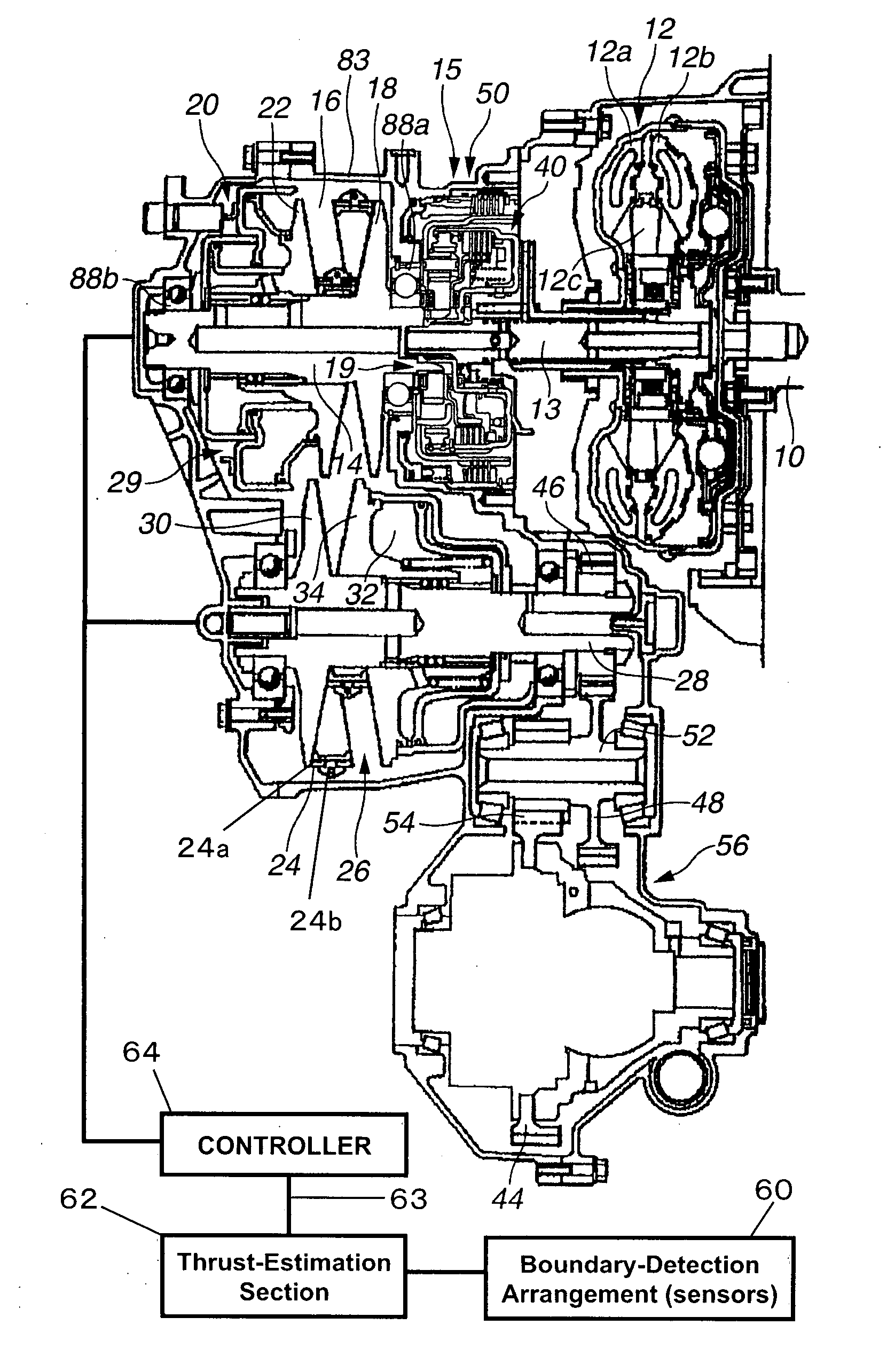
[0026]Referring initially to FIG. 1, a V-belt continuously variable is illustrated in accordance with a first embodiment of the present invention. FIG. 1 is a cross sectional view of the continuously variable V-belt transmission. This continuously variable transmission is connected to an output shaft 10 of an engine to transmit rotation of the output shaft 10 of the engine to a drive wheel (not shown). The continuously variable transmission includes, among other components, a torque converter (start mechanism) 12, a driving shaft (an output shaft) 14, a forward reverse changeover mechanism 15, a V-...


PUM


Abstract

A continuously variable V-belt transmission basically has a driving pulley, a driven pulley and a V-belt wound around the pulleys. The frictional engagement between the pulleys and the V-belt is controlled by regulating pulley axial thrusts to the pulleys. The V-belt has a plurality of torque transmitting connected by an annular ring. A boundary-detection arrangement is provided to detect a boundary position between a first region, in which the elements are arranged without any gap therebetween, and a second region, in which the elements are arranged with a gap therebetween, along a portion of the driving pulley when torque is being transmitted. The detected boundary position is used to estimate the pulley axial thrust applied by the driving pulley against the V-belt, and to control the pulley axial thrust to a lower limit which ensures that the V-belt will not slip upon application of the maximum torque.

Description

CROSS-REFERENCE TO RELATED APPLICATIONS[0001]This application claims priority to Japanese Patent Application No. 2006-065723, filed on Mar. 10, 2006. The entire disclosure of Japanese Patent Application No. 2006-065723 is hereby incorporated herein by reference.BACKGROUND OF THE INVENTION[0002]1. Field of the Invention[0003]The present invention generally relates to continuously variable V-belt transmissions. More specifically, the present invention relates to determining the thrust to be applied to a pulley of a continuously variable V-belt transmission.[0004]2. Background Information[0005]Conventional continuously variable V-belt transmissions basically have a driving pulley that receive an input torque from the engine, a driven pulley that outputs torque to a drive wheel and a V-belt that winds around the driving and driven pulleys to transmit rotation from the driving pulley to the driven pulley. In particular, the input torque to the driving pulley is transmitted from the drivi...

Claims


Application Information

Patent Timeline
Patent Type & Authority Applications(United States)
IPC IPC(8): F16H55/56
CPCY10T477/623F16H61/66272
Inventor TANAKA, HIROAKITAGUCHI, MASANORIMOMOI, MAKOTO
Owner JATCO LTD
Why Eureka
Try Eureka