Auxiliary mounting stabilizer

a technology mounting bracket, which is applied in the direction of mechanical control devices, instruments, foot actuation initiation, etc., can solve the problems of inconvenient installation of auxiliary brake pedal in cars, difficulty in installing auxiliary brake pedals, undesirable consequences, etc., and achieve the effect of resisting slippag

Active Publication Date: 2019-06-25
RIEBER MICHAEL S
View PDF12 Cites 0 Cited by
  • Summary
  • Abstract
  • Description
  • Claims
  • Application Information

AI Technical Summary

Benefits of technology

[0016]A related object of the invention is to provide a platform for carrying an auxiliary brake pedal in a car or similar vehicle, wherein the platform is convertible into an efficient configuration for shipping.
[0017]According to the invention, an auxiliary brake stabilizer carries an instructor's brake in a given car. The support interacts with both the floor section and the firewall section of the car in front of the passenger seat, without necessarily being secured to these sections by penetrating fasteners. The brake support fits against a firewall of a car and is elevated with respect to the firewall to carry the brake over a passage with open lateral edges and supporting standoffs at top and bottom edges of the platform. A massive anchor plate rests against the floor at the base of the firewall to resist slippage. A hinged connection between the platform and anchor plate allow precise fit with the configuration of the car, while allowing the support to fold into a compact shipping configuration.

Problems solved by technology

Second, during an intermediate stage, the newly licensed driver may drive while unsupervised, but for a given period of time he is subject to various limitations applicable to higher risk situations.
For example, the newly licensed driver may be prohibited from driving at night and may be limited in driving with passengers.
Still, installing an auxiliary brake pedal in a car presents difficulty and undesirable consequences, because cars are not designed to accommodate auxiliary brake pedals.
These systems using a crossbar do not appear to be useful or practical in many current vehicles.
Consequently, a design using a crossbar is ill-suited for use in many modern cars.
Also, it would seem that in any era of car design, a crossbar might interfere with the driver's use of the accelerator pedal, which is well known to be located on the passenger's side of the main brake pedal where the crossbar would have to pass it in order to connect to the main brake pedal.
The above-described technology may have been limited to an earlier era, to any vehicles that perhaps have a flat floor across the vehicle and an accelerator pedal that luckily is not an obstacle to the crossbar.
While crossbar designs may be impractical, prior designers were attempting to create a desirable result by loose-laying the passenger's side support for the crossbar.
Bolting the instructor's brake pedal to the floor of the car is undesirable because it causes damage to the car.
With cables replacing rods to interconnect the pedals of a dual brake system, there is increased chance that the instructor's loose laid brake pedal or its loose laid supporting platform will become dislocated.
From another perspective, the instructor's brake pedal might shift up, down, or sideways while being applied, which may produce undesirable consequences in the effectiveness of applying the instructor's brake.

Method used


Image

  • Auxiliary mounting stabilizer
  • Auxiliary mounting stabilizer
  • Auxiliary mounting stabilizer

Examples


Embodiment Construction

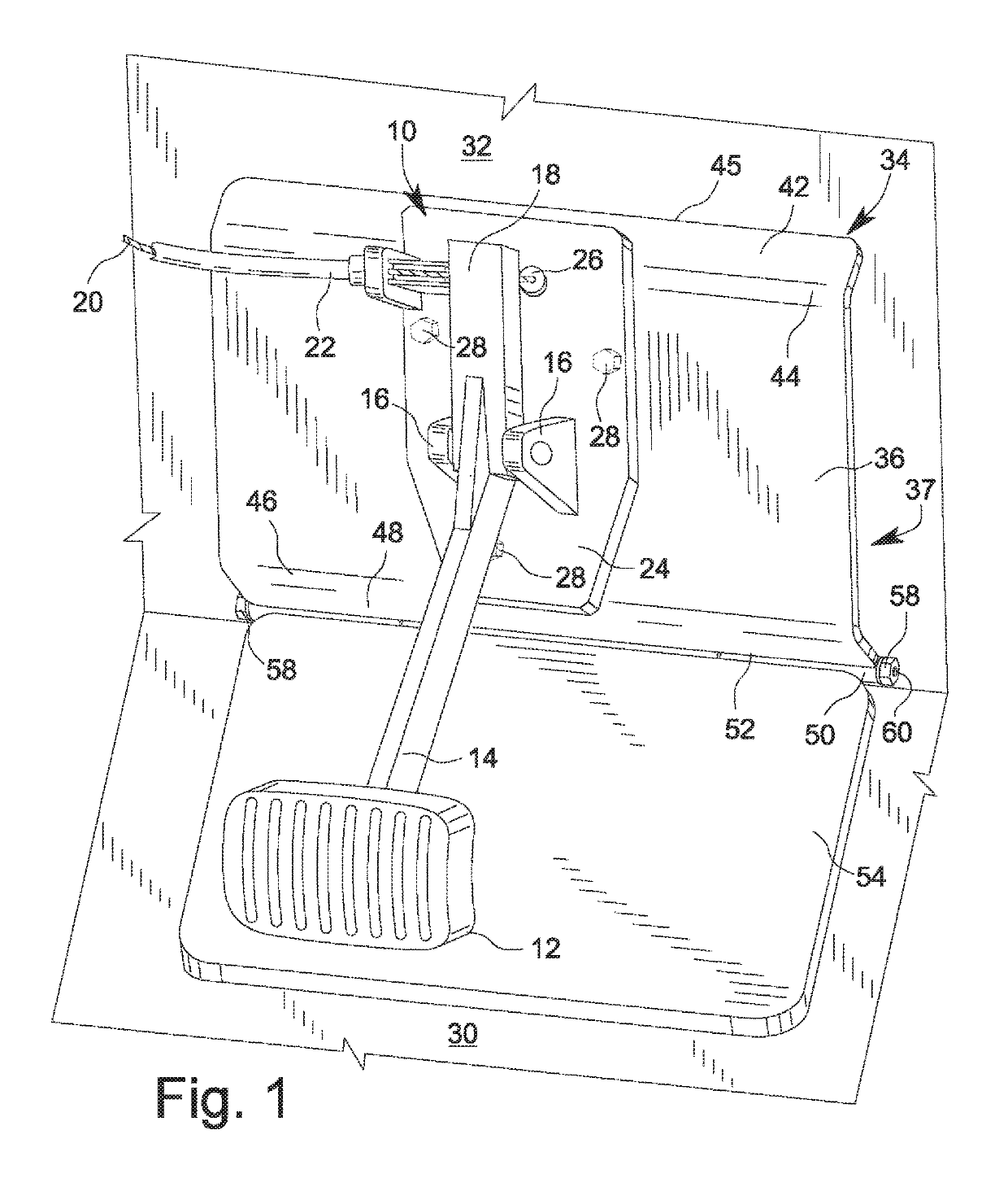
[0024]The invention is directed to improvements in auxiliary braking systems in cars and other vehicles where a person other than the driver is provided with a second, supplemental, or auxiliary brake control. For purposes of description, a car will be described as having a main brake pedal and main controls. The main brake is the brake pedal at the driver's position. Similarly, the main controls are controls at the driver's position. Main controls, including a main brake, typically are those that are original equipment on the car, such as those installed at traditional locations during manufacture of the car at the driver's position. An auxiliary brake or supplemental brake typically refers to a brake applicator or pedal at the front seat passenger's position, although it would be possible to have an auxiliary brake mounted anywhere in the car. An auxiliary brake also can be regarded as being a brake other than the main brake and that operates by applying the main brake pedal throu...


PUM


Abstract

An auxiliary brake stabilizing support carries an instructor's brake in a given car. The support interacts with both the floor section and the firewall section of a car in front of the passenger seat, without necessarily being secured to these sections by penetrating fasteners. The brake support fits against a firewall of a car and is elevated with respect to the firewall to carry the brake over a passage with open lateral edges and supporting standoffs at top and bottom edges of the platform. A massive anchor plate rests against the floor at the base of the firewall to resist slippage. A hinged connection between the platform and anchor plate allow precise fit with the configuration of the car, while allowing the stabilizing support to fold into a compact shipping configuration.

Description

BACKGROUND OF THE INVENTIONField of the Invention[0001]The invention generally relates to a machine element or mechanism and more specifically to control lever and linkage systems. In another aspect, the invention relates to vehicle brake control systems or parts thereof and brake action initiating means with foot actuated disposition of the pedal. In a further aspect, the invention relates to vehicle fittings. More specifically, the invention is directed to double foot controls, e.g., for instruction vehicles.Description of Related Art[0002]The conditions for operating a motor vehicle on public roads are controlled by law. Each state is entitled to establish the conditions precedent for a new driver to obtain driving privileges. State laws often follow a Graduated Driver Licensing (GDL) program. While the details of conditions established in the various states following a GDL program might vary, the required steps for a new driver to become entitled to drive often are categorized i...

Claims


Application Information

Patent Timeline
Patent Type & Authority Patents(United States)
IPC IPC(8): G05G1/34B60T7/06B60K23/00
CPCB60T7/06G05G1/34B60K2023/005
Inventor RIEBER, MICHAEL S.
Owner RIEBER MICHAEL S
Why Eureka
Try Eureka