
Event-based process configuration

a technology of event-based process and configuration, applied in the field of event-based computer systems, can solve the problems of time-consuming and labor-intensive construction of such event-based system or process, inability to adapt to various types of real-time, and inability to implement sequential programming languages. to achieve the effect of facilitating the configuration and modification of event-based processes and efficiently modifying or configuring event-based processes

Active Publication Date: 2008-08-14
SOFTWARE AG
View PDF108 Cites 56 Cited by
  • Summary
  • Abstract
  • Description
  • Claims
  • Application Information

AI Technical Summary

Benefits of technology

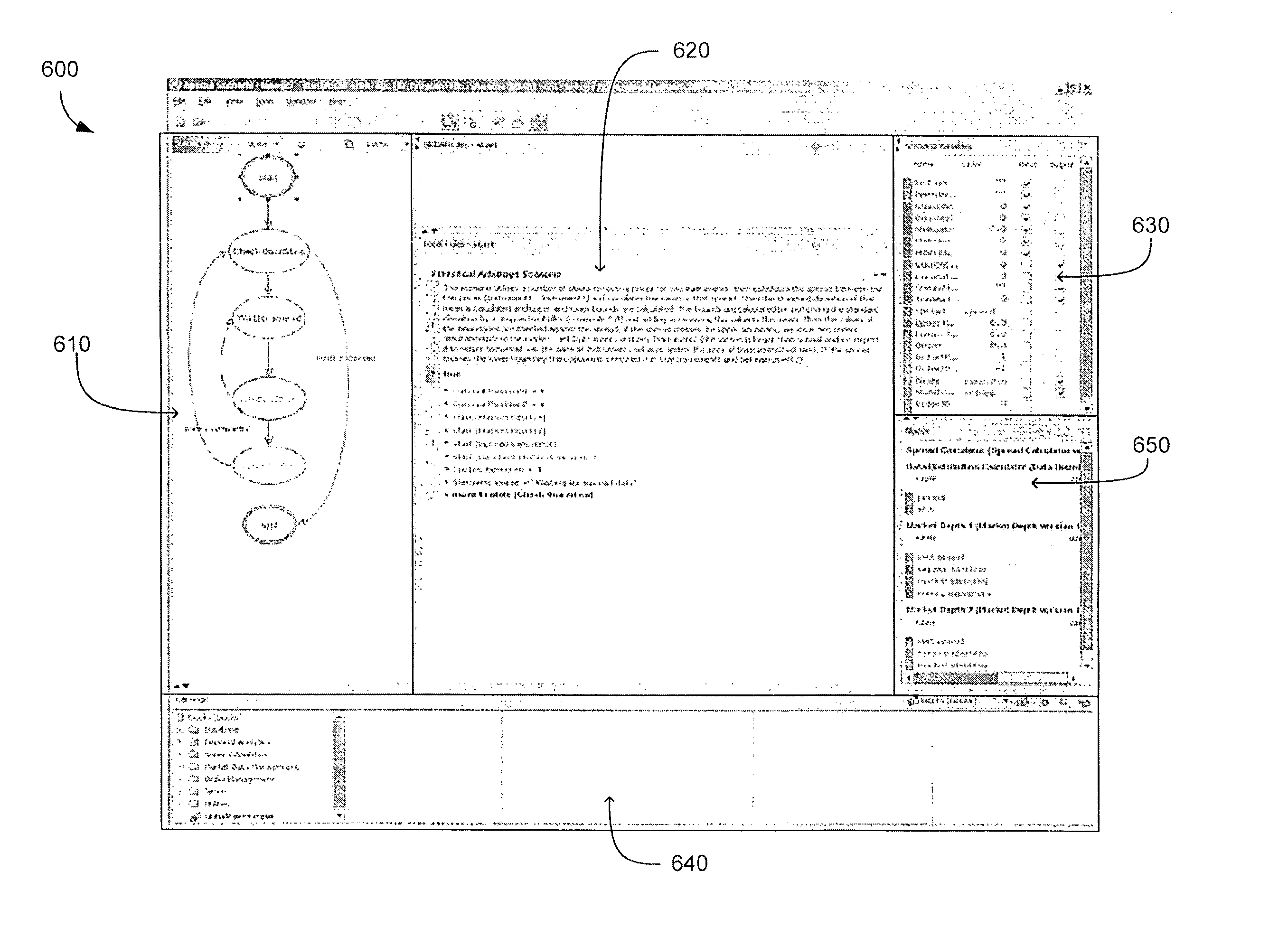
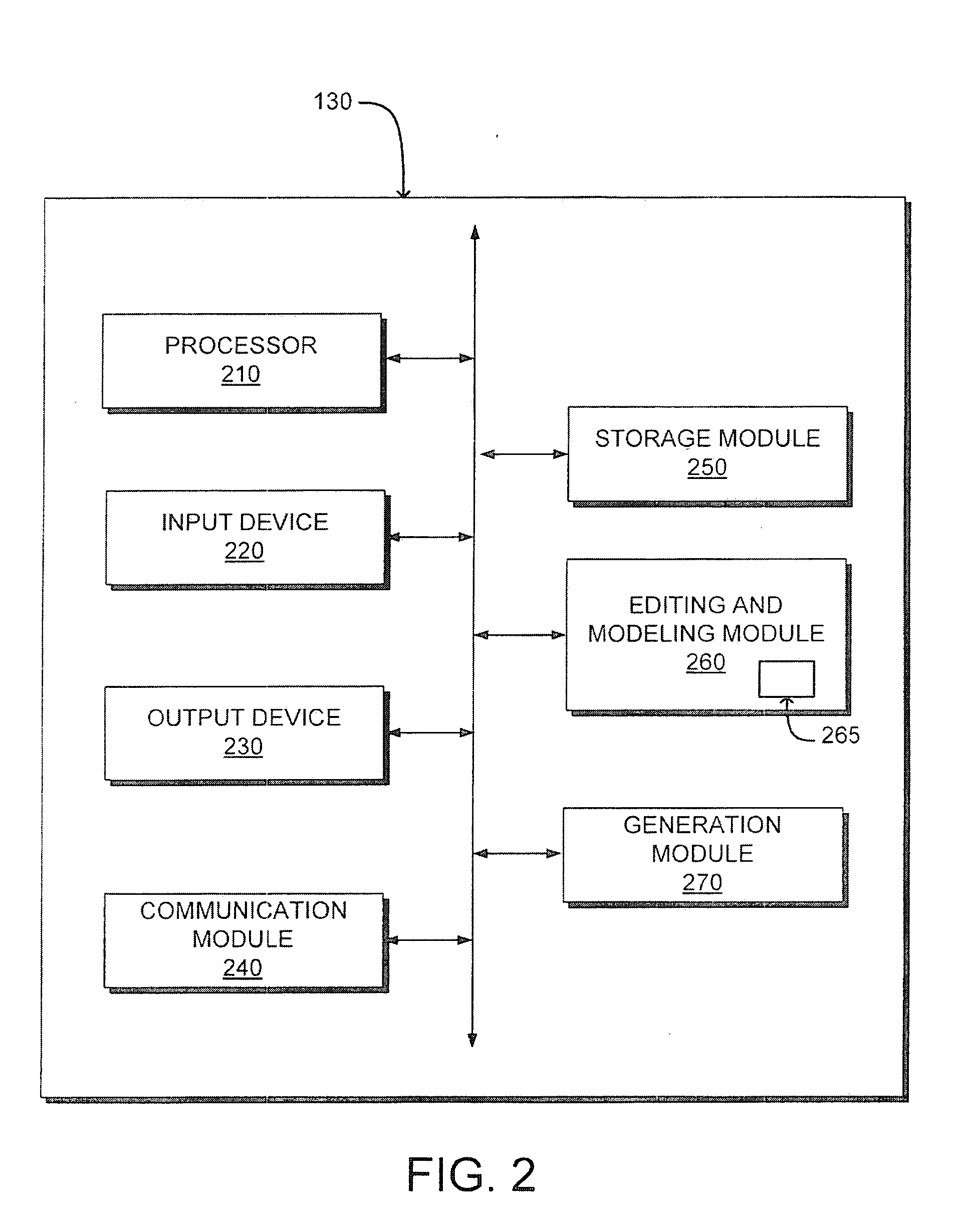
[0070]The configuration module 130 first receives 510 a description of the event-based process. For example, the configuration module 130 receives 510 a graphical depiction of the event-based process, such as a state transition diagram including rules for transitioning between states. This allows description of an event-based process using a simple graphical interface depicting relationships between different states rather than using a text-based programming language having multiple syntax requirements. The configuration module 130 then generates 520 executable data from the event-based process description. Hence, the configuration module 130 allows executable data for implementing the event-based process to be generated from a simplified description of the event-based process. This simplifies configuration and modification of event-based processes.
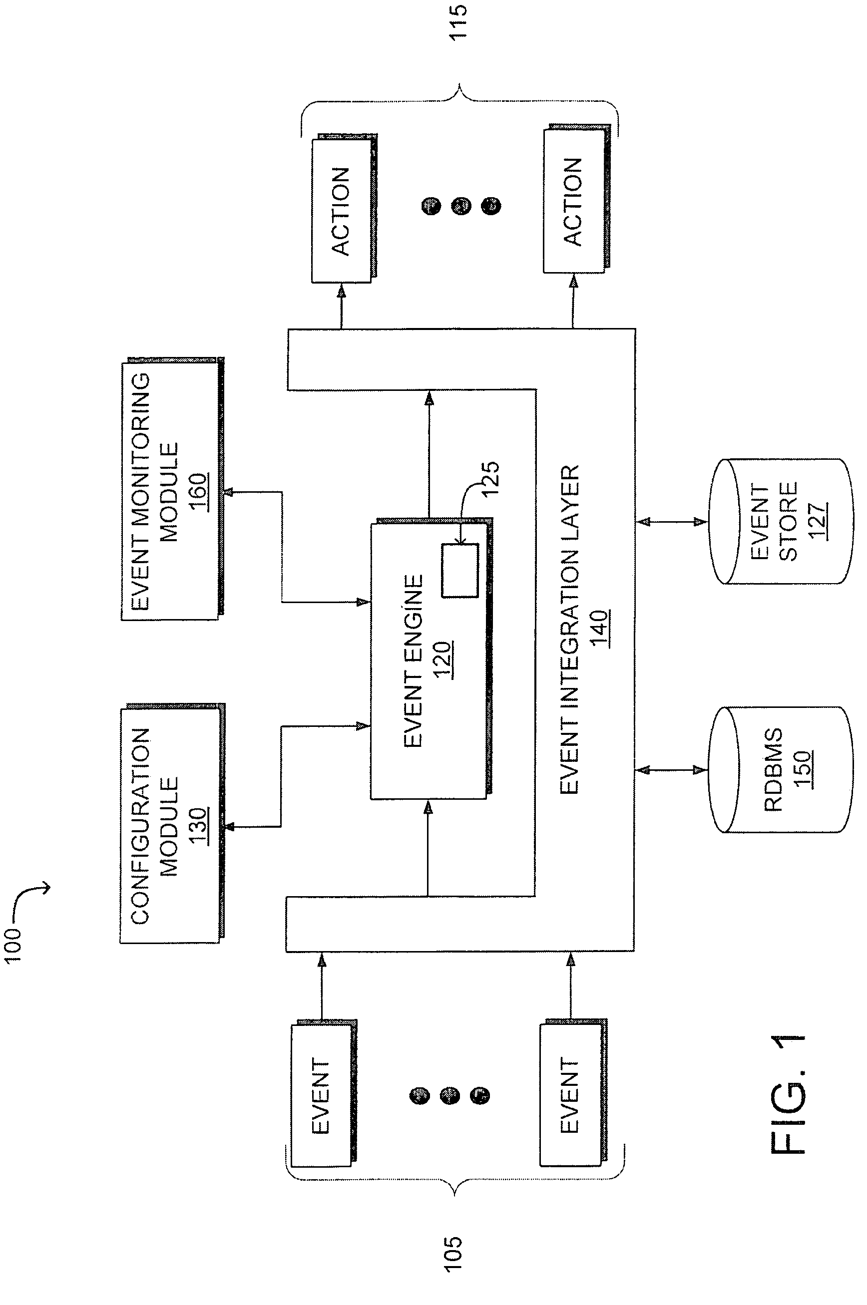
[0071]A connection, such as a data connection, is then established 530 between the configuration module 130 and the event engine 120. In one embodiment, the configuration module 130 and event engine 120 reside at remote locations. This allows a configuration module 130 to modify or configure event-based processes operating on multiple event engines 120. The generated executable data is then transmitted 535 from the configuration module 130 to the event engine 120 using the established connection. The event engine 120 then configures 540 the event-based process using the executable data. For example, the event engine 120 generates a new event-based process or modifies an existing event-based process (e.g., alters existing state transition rules, creates additional state transition rules, adds execution operations to existing states, removes execution operations from existing states or similar modifications) responsive to the received executable data. This allows the event engine 120 to efficiently modify or configure the event-based process upon receiving data from the configuration module 130 rather than requiring additional data processing or formatting by the event engine 120.

Problems solved by technology

However, conventional computer systems, such as database systems, are not designed for such real-time event monitoring, analysis and response.
Although conventional sequential programming languages, such as C++ or Java™ allow construction of customized systems for event detection and response, constructing such an event-based system or process is time-intensive and the inherent sequential nature of such programming languages is not suitable for various types of real-time event monitoring, analysis and response.
However, there are no standard development tools and techniques for creating and deploying event-based BAM applications.
Conventional development methods require use of a bespoke-based method, resulting in a long development cycle and a difficult to maintain system.
Conventional development techniques also cannot uniformly abstract multiple applications or scenario types, distinguish between different input parameters and support streaming output parameters.

Method used


Image

  • Event-based process configuration
  • Event-based process configuration
  • Event-based process configuration

Examples


Embodiment Construction

[0024]A system and method for configuring an event-based process, such as generating an event-based process or modifying an event-based process responsive to an input, are described. For purposes of explanation, numerous specific details are set forth in order to provide a thorough understanding of the invention. It will be apparent, however, to one skilled in the art that the invention can be practiced without these specific details. In other instances, structures and devices are shown in block diagram form in order to avoid obscuring the invention.

[0025]Reference in the specification to “one embodiment” or “an embodiment” means that a particular feature, structure, or characteristic described in connection with the embodiment is included in at least one embodiment of the invention. The appearances of the phrase “in one embodiment” in various places in the specification are not necessarily all referring to the same embodiment.

[0026]Some embodiments may be described using the expres...


PUM


Abstract

A system and method for configuring an event-based process are disclosed. A configuration module receives input describing an event-based process or modifications to an event-based process. For example, the configuration module receives as input a graphical depiction of one or more states and state transitions that comprise at least a portion of the event-based process. Using the received input description, the configuration module generates executable data, such as data formatted as an event processing language, corresponding to the input. The executable data is then communicated to an event engine which executes the executable data to implement the event-based process or modifications to an event-based process corresponding to the received input. One or more aspects of the execution of the event-based process may also be visualized, and graphically modified, though an event monitoring module.

Description

CROSS REFERENCE TO RELATED APPLICATIONS[0001]This application claims priority under 35 U.S.C. § 119(e) from U.S. Provisional Application No. 60 / 888,495, titled “A Technique And Process To Develop And Deploy Event-Driven Architectures, Using-Direct Manipulation Tools,” filed Feb. 6, 2007, and U.S. Provisional Application No. 60 / 896,266, titled “A Process For The Graphical Modeling, Construction And Deployment Of Complex Event Processing Business Activity Monitoring Processes,” filed Mar. 21, 2007, which are incorporated by reference herein in their entirety.BACKGROUND[0002]1. Field of Art[0003]The present invention generally relates to the field of event-based computer systems, and more specifically, to managing and configuring complex event processing (CEP) applications.[0004]2. Description of the Related Art[0005]Recently, the availability and amount of real-time information has significantly increased. This allows businesses to monitor events in real time and to automatically resp...

Claims


Application Information

Patent Timeline
Patent Type & Authority Applications(United States)
IPC IPC(8): G06F9/44G06F3/048
CPCG06F9/542G06Q40/04G06Q10/08
Inventor BATES, JOHNSMITH, GARETHBENTLEY, RICHARD M.
Owner SOFTWARE AG
Learn More