Differential amplifier and display device using the same

a technology of display device and amplifier, which is applied in the direction of differential amplifier, amplifier with semiconductor device/discharge tube, dc-amplifiers with dc-coupled stages, etc., can solve the problems of inability to achieve rail-to-rail operation, inability to achieve input in the vicinity of a positive power supply voltage, and difficulty in achieving higher accuracy. , to achieve the effect of improving the device between output amplifiers of display data drivers and improving accuracy

Active Publication Date: 2007-07-12
RENESAS ELECTRONICS CORP
View PDF8 Cites 13 Cited by
  • Summary
  • Abstract
  • Description
  • Claims
  • Application Information

AI Technical Summary

Benefits of technology

[0053] According to the present invention, by adopting the depletion-type MOS transistors in an input differential stage, it becomes possible to receive an input voltage as from a negative supply voltage. Further, according to the present invention, a deviation among output amplifiers in a display data driver is improved, thereby allowing achievement of higher accuracy.

Problems solved by technology

For this reason, the characteristic with respect to the amplitude difference deviation described before may become deteriorated, thereby making it difficult to achieve higher accuracy.
On the other hand, with this conventional differential amplifier, owing to the threshold voltage of a minus value, an input in the vicinity of a positive power supply voltage becomes impossible, as a result of which the rail-to-rail operation cannot be achieved.

Method used


Image

  • Differential amplifier and display device using the same
  • Differential amplifier and display device using the same
  • Differential amplifier and display device using the same

Examples


examples

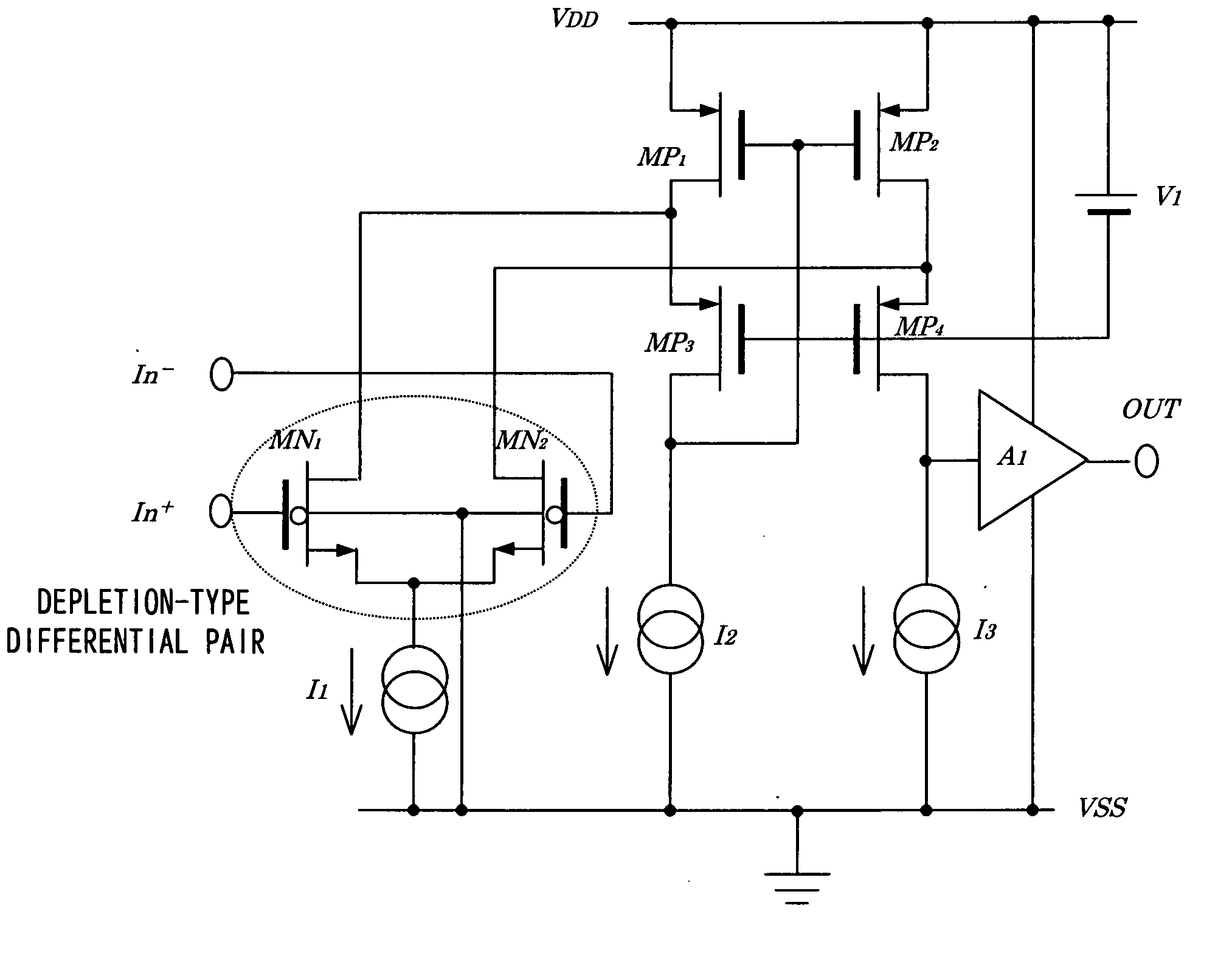
[0096]FIG. 10 is a schematic sectional view of a depletion-type N-channel MOS transistor in an embodiment of the present invention. Referring to FIG. 10, N-type source and drain regions are formed in a P-type semiconductor substrate, while a channel region is not subjected to ion-implantation of P-type impurity (also termed HV (high voltage) P-well) and is held in a substrate impurity concentration (referred to as ‘non-dope’). The so formed N-channel MOS transistor exhibits a deletion characteristic, depending on the condition with regard to source impurity and substrate impurity concentration and has a threshold voltage of about −0.1 volt. When an negative power supply voltage is applied to a back gate of the N-channel MOS transistor, the so called back gate effect is obtained. As well known, a the back-gate effect indicate an effect in which a threshold voltage of a MOS transistor is varied in accordance with a potential difference between a source and a back gate of the MOS trans...


PUM


Abstract

Disclosed is a differential amplifier which comprises a differential pair comprising depletion-type first and second N-channel MOS transistors, a first current source that supplies a current for the differential pair, a current mirror circuit formed by transistor pairs connected in cascode fashion in two stages, for connecting an output pair of the differential pair in folded connection, second and third current sources connected to an input terminal of the current mirror circuit and an output terminal of the current circuit, respectively, and a buffer amplifier with that has an input terminal connected to the output terminal of the current mirror circuit and has an output terminal connected to an output terminal of the differential amplifier.

Description

FIELD OF THE INVENTION [0001] The present invention relates to a differential amplifier. More specifically, the invention relates to a configuration of a differential amplifier suitable for use as a drive amplifier for a data driver of a liquid crystal display device or the like and a display device including the differential amplifier. BACKGROUND OF THE INVENTION [0002] In recent years, a reduction in the cost of color display devices has been achieved. Accompanying the cost reduction, the cost of LCD (Liquid Crystal Display) source drivers has reduced to almost a third during these ten years, and a demand for further cost reduction has been increasing. In order to satisfy the demand as described above, reduction in a chip size of an LSI of the LCD source driver is planned in research, product design, and the like. It is because the most effective means for the cost reduction is the chip size reduction. [0003] The number of gray scales has been increased, and a transition is made f...

Claims


Application Information

Patent Timeline
Patent Type & Authority Applications(United States)
IPC IPC(8): H03F3/45
CPCH03F3/3022H03F3/45192H03F3/45744H03F2203/45684H03F2203/45281H03F2203/45342H03F2203/45354H03F2203/45236
Inventor NISHIMURA, KOUICHISHIMATANI, ATSUSHIMURATA, TOSHIKAZU
Owner RENESAS ELECTRONICS CORP
Why Eureka
Try Eureka