Eureka AIR delivers breakthrough ideas for toughest innovation challenges, trusted by R&D personnel around the world.

Photovoltaic modules with a thermoplastic hot-melt adhesive layer and a process for their production

a thermoplastic hot-melt adhesive and photovoltaic module technology, applied in the direction of photovoltaic energy generation, film/foil adhesives, photovoltaics, etc., can solve the problems of affecting the output of the module, and affecting the production process. , to achieve the effect of low weight, fast and inexpensive process for the production

Inactive Publication Date: 2007-06-14
STOLLWERCK GUNTHER +5
View PDF6 Cites 197 Cited by
  • Summary
  • Abstract
  • Description
  • Claims
  • Application Information

AI Technical Summary

Benefits of technology

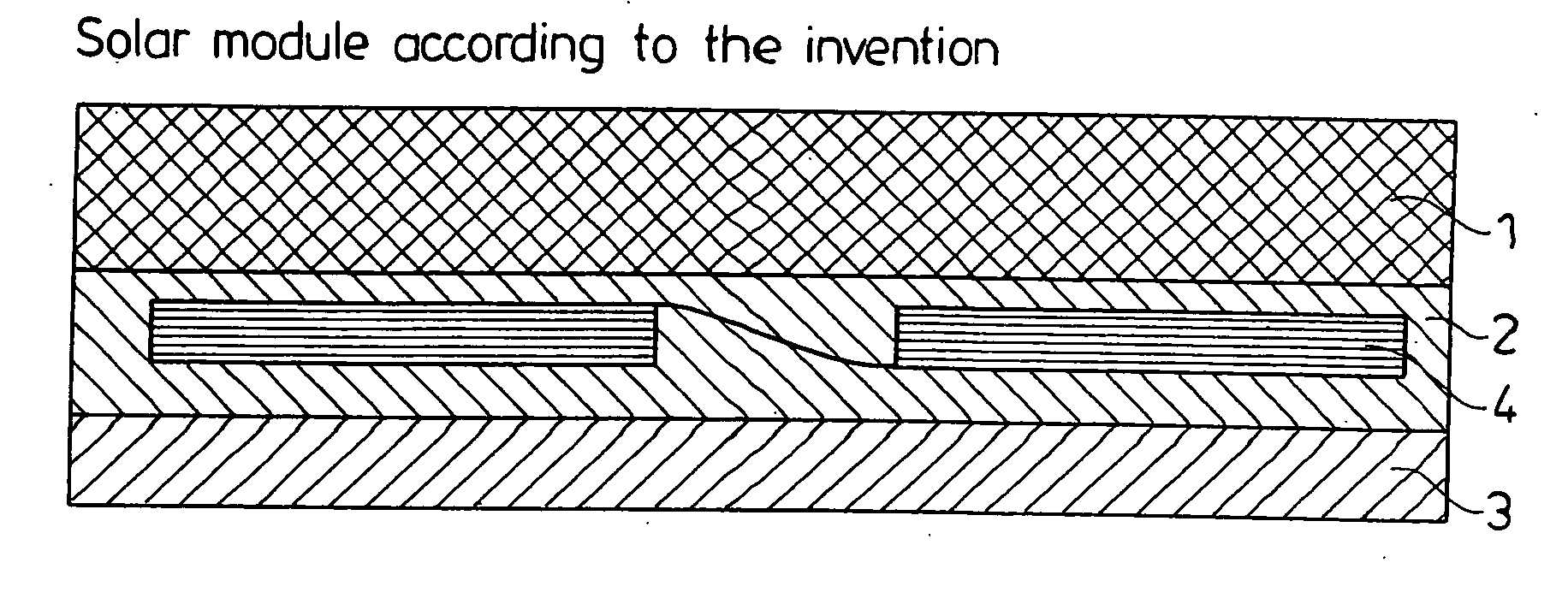
[0018] The object of the invention was to provide photovoltaic modules which are distinguished by a fast and inexpensive process for their production and a low weight.
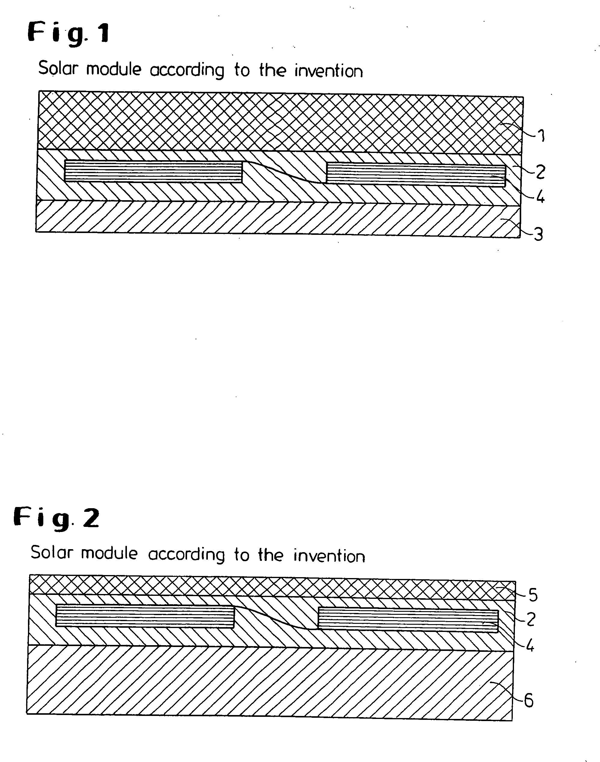
[0021] A) at least one outer covering layer on the front side, facing the energy source, of glass or an impact-resistant, UV-stable, weathering-stable, transparent plastic with a low permeability to water vapor,

Problems solved by technology

The solar cells, themselves, are not attacked by water vapor or oxygen, but corrosion of the metal contacts and a chemical degradation of the EVA embedding material occurs.
A destroyed solar cell contact leads to a complete failure of the module, since all the solar cells in a module are usually electrically connected in series.
Degradation of the EVA manifests itself in a yellowing of the module, together with a corresponding reduction in output due to absorption of light and a visual deterioration.
With 30% of the total costs, a relatively high proportion of the production costs for photovoltaic modules falls to the module construction.
This high proportion of the module production is due to high material costs (hail-proof front glass 3 to 4 mm thick, composite film on the reverse side) and to long process times, i.e. low productivity.
Because of the relatively thick front glass pane (3 to 4 mm), conventional solar modules, furthermore, are heavy, which in turn necessitates stable and expensive holding constructions.
The removal of heat in the case of the solar modules of today also is solved only unsatisfactorily.
In full sunlight, the modules heat up to 80° C., which leads to a temperature-related deterioration in the efficiency of the solar cells and therefore, in the end, an increase in the cost of the solar current.
Various set-ups to reduce the module production costs by less expensive production processes have not so far been accepted.
The films mentioned are neither impact-resistant enough nor sufficiently stable to weathering, nor is the adhesive layer flexible enough in order to provide effective mechanical protection for the highly fragile solar cells.
Gluing is effected with the aid of vacuum, which, as already described above, requires long process times. Furthermore, a vacuum laminator can no longer be employed from a module size of 2 m2, since the path for the air bubbles to escape at the edge is too long, so that they can no longer escape during the conventional process time and are “frozen” in the adhesive.
This results in losses due to reflection.
The thermoplastic polyurethanes described in JP-A 09-312410 indeed soften during heating in a vacuum vessel, but they are not sufficiently liquid for the intermediate spaces between the solar cells to be filled up.
Unusable solar modules are obtained as a result.
However, the adhesive layer also must not be too flexible in order to impart to the entire solar module composite a still sufficient mechanical distortion rigidity.

Method used


Image

  • Photovoltaic modules with a thermoplastic hot-melt adhesive layer and a process for their production
  • Photovoltaic modules with a thermoplastic hot-melt adhesive layer and a process for their production
  • Photovoltaic modules with a thermoplastic hot-melt adhesive layer and a process for their production

Examples


example 1

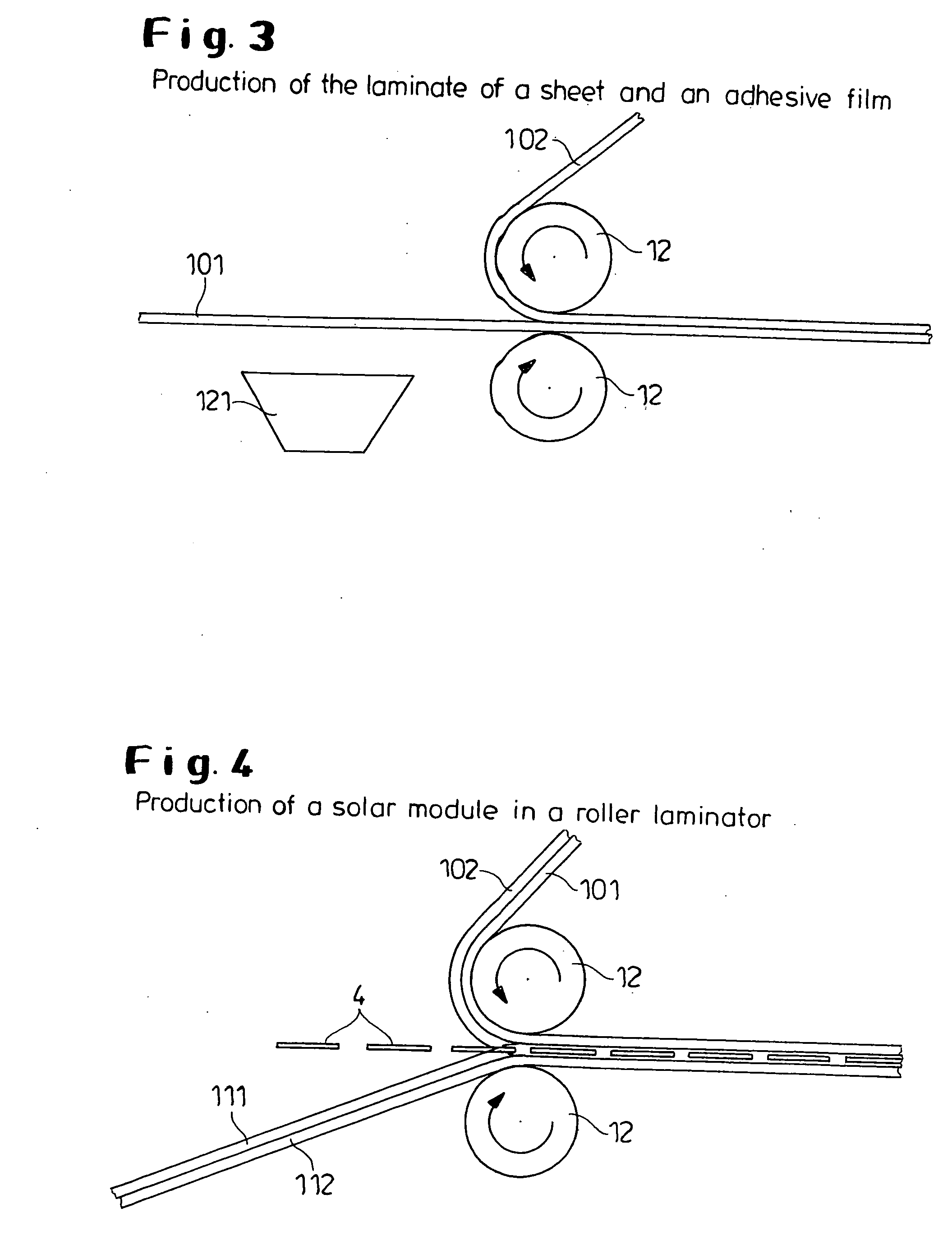
[0080] A film of Texin® DP7-3007 (commercial product from Bayer Corp., hardness: 58 Shore D) was extruded on to a Makrofol® film as follows: A vertical die arrangement was attached to an extruder with a roll unit from Reifenhäuser (with a chill roll). The casting roll of the unit was preceded by a backing roll with a rubber-covered surface. The die was positioned between the casting roll and backing roll. To achieve a wind-up speed which is very slow for this “chill roll” unit, the film composite was taken off by only one winder. To improve the adhesion of the Texin® melt to the Makrofol® film DE 1-1 employed (with a thickness of 375 μm (commercial product of Bayer AG)), the Makrofol® film was preheated with IR lamps before feeding in the melt. The Texin® was predried in a dry air dryer for 6 h at 60° C.

[0081] The following processing parameters were established:

Die temperature180°C.Material temperature of the Texin ®186°C.Pressure before the die75barSpeed of rotation of the extr...

example 2

[0086] A film was extruded using Desmopan® 88 382 (commercial product from Bayer AG, hardness:80 Shore A) as follows:

[0087] A horizontal die arrangement was attached to an extruder with a roll unit from Somatec (with a chill roll). The chill roll was positioned about 5 cm below the die.

[0088] To achieve a wind up speed which is very slow for this “chill roll” unit, the film was taken off by only one winder. The Desmopan® was predried in a dry air dryer for 6 h at 75° C.

[0089] The following processing parameters were established:

Die temperature170°C.Material temperature of the Texin ®177°C.Pressure before the die27barSpeed of rotation of the extruder40rpmTemperature at the chill roll10°C.Wind up speed1.7m / min

[0090] The film produced in this way was then used as an adhesive layer in a solar module as described in FIG. 1. The top side of the module (15×15 cm2) was made of hardened white glass and the reverse side of a composite film (Tedlar-PET-Tedlar). The solar modules were prod...


PUM

PropertyMeasurementUnit
Temperatureaaaaaaaaaa
Thicknessaaaaaaaaaa

Abstract

The invention relates to photovoltaic modules with a specific thermoplastic adhesive layer and the production thereof.

Description

[0001] This application is a divisional of U.S. Ser. No. 10 / 266,212 which was filed Oct. 8, 2002.FIELD OF THE INVENTION [0002] The invention relates to photovoltaic modules with a specific thermoplastic adhesive layer and their production. BACKGROUND OF THE INVENTION [0003] Photovoltaic modules or solar modules are understood as meaning photovoltaic structural elements for direct generation of electric current from light, in particular sunlight. Key factors for a cost-efficient generation of solar currents are the efficiency of the solar cells used and the production costs and life of the solar modules. [0004] A solar module conventionally contains a composite of glass, a circuit of solar cells, an embedding material and a reverse side construction. The individual layers of the solar module have to fulfill the following functions: [0005] The front glass (top layer) is used for protection from mechanical and weathering influences. It must have a very high transparency in order to kee...

Claims


Application Information

Patent Timeline
IPC IPC(8): H02N6/00C08G18/65H01L31/04H01L31/048
CPCB32B17/10009B32B17/1077H01L31/048Y02E10/50H01L31/0481C09J7/00
Inventor STOLLWERCK, GUNTHERHASSLER, CHRISTIANFOLTIN, ECKARDOPELKA, GERHARDPOST, BERNDHATTIG, JURGEN
Owner STOLLWERCK GUNTHER
Why Eureka
Eureka Blog
Learn More