
Heating apparatus

Inactive Publication Date: 2007-06-07
KOBE STEEL LTD
View PDF3 Cites 9 Cited by
  • Summary
  • Abstract
  • Description
  • Claims
  • Application Information

AI Technical Summary

Benefits of technology

[0013] Therefore, the present invention has been made in view of the above problems, and it is an object of the present invention to provide a heating apparatus that is so designed as to heat an object to be heated which has a large area and is formed into a shape of a substrate such as a silicon wafer through induction heat generation of a heat generating part made of glasslike carbon and that can rapidly raise or lower the temperature without contamination of the object.
[0019] The heating apparatus according to the present invention includes a heating container for receiving an object to be heated. The container is constructed such that at least a portion of the container, specifically, a portion approximately formed into a shape of a plate, is made of glasslike carbon, and the plate-shaped portion of the container serves as a heat generating part. The heating apparatus further includes a high-frequency plate-shaped coil, which is disposed at the outside of the container while the coil is adjacent and is opposed to the heat generating part of the container. The coil is wound approximately into a shape of a plate. Consequently, when electric current is supplied to the coil, heat can be generated from the heat generating part with good heat distribution through induction heat generation of the heat generating part. As a result, it is possible to emit heat to the object which has a large area and is formed into a shape of a substrate (a plate) such as a silicon wafer with high directivity, and therefore, to rapidly raise the temperature of the object, whereby the object is rapidly heated. In addition, the heat generating part is made of glasslike carbon, which does not generate any gaseous contaminant or dust even at high temperature, and has even high chemical resistance, while the remaining part of the container except for the heat generating part does not generate heat. Consequently, it is possible to heat the object without contaminating the object. Since the heat generating part is made of glasslike carbon, which has a small heat capacity, after the heat treatment, the heat generating part can be easily cooled by an appropriate means such as blowing cooling nitrogen gas to the heat generating part, and therefore, it is possible to rapidly lower the temperature of the object in the container.
[0020] The heating apparatus according to the present invention further includes a container-outside gas atmosphere control means for controlling the outside of the container to be maintained at an inert gas atmosphere. Consequently, it is possible to prevent the oxidative degradation of the heat generating part made of glasslike carbon even at relatively high temperature.
[0021] The heating apparatus according to the present invention further includes a heat insulation member and / or a reflection member disposed between the heat generating part and the coil. Consequently, it is possible to greatly reduce the temperature-raising time of the object, and therefore, to greatly increase the heating efficiency. Also, the effect is accomplished only by the heat generating part without the entirety of the heating apparatus being covered, and therefore, even the temperature-lowering speed can be secured.
[0022] Furthermore, in the case of the heating apparatus wherein the ratio (R2 / R1) of the emissivity (R2) of the inner surface of the heat generating part to the emissivity (R1) of the outer surface of the heat generating part is 1.2 or more, it is possible to increase the emissivity (R2) of the inner surface of the heat generating part facing the inside of the container in which the object is disposed to be greater than the emissivity (R1) of the outer surface of the heat generating part facing the outside of the container, like the above-mentioned ratio. As a result, the ratio of the heat emission from the container to the outside to the heat generated by induction heating is decreased. Consequently, it is possible to greatly reduce the temperature-raising time of the object, and therefore, to greatly increase the heating efficiency.

Problems solved by technology

However, the above-described combination has a problem in that the container has a certain heat insulation effect and therefore, is not necessarily suitable for a method of rapidly raising the temperature of the object, and heating the object in a very short period of time and then instantly lowering the temperature of the object.
As a result, it is difficult to accomplish satisfactory heating efficiency and uniform heating of the object.
Consequently, the method of generating heat from the cylindrical body through induction heat generation is not suitable to heat the object having a large area.
However, the susceptor 73 and the silicon wafer 72 are in contact with each other, which may cause a relatively large temperature fluctuation in the wafer and contamination of the wafer.
Furthermore, since the reaction container has a certain heat insulation effect, it is difficult to rapidly decrease the temperature of the silicon wafer 72.

Method used


Image

  • Heating apparatus
  • Heating apparatus
  • Heating apparatus

Examples


examples 1 and 2

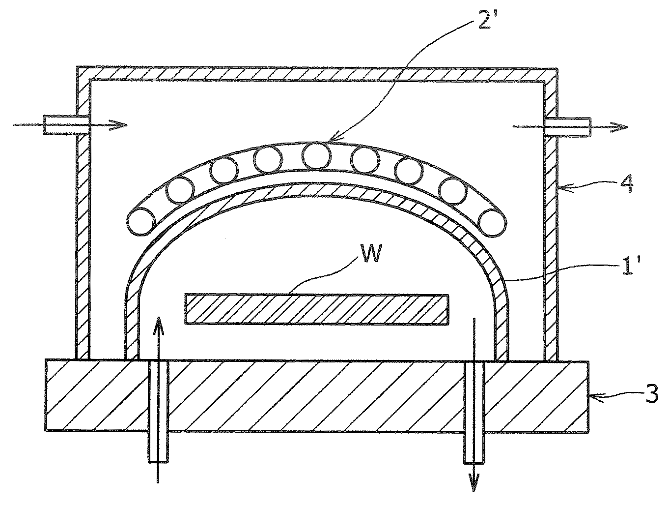
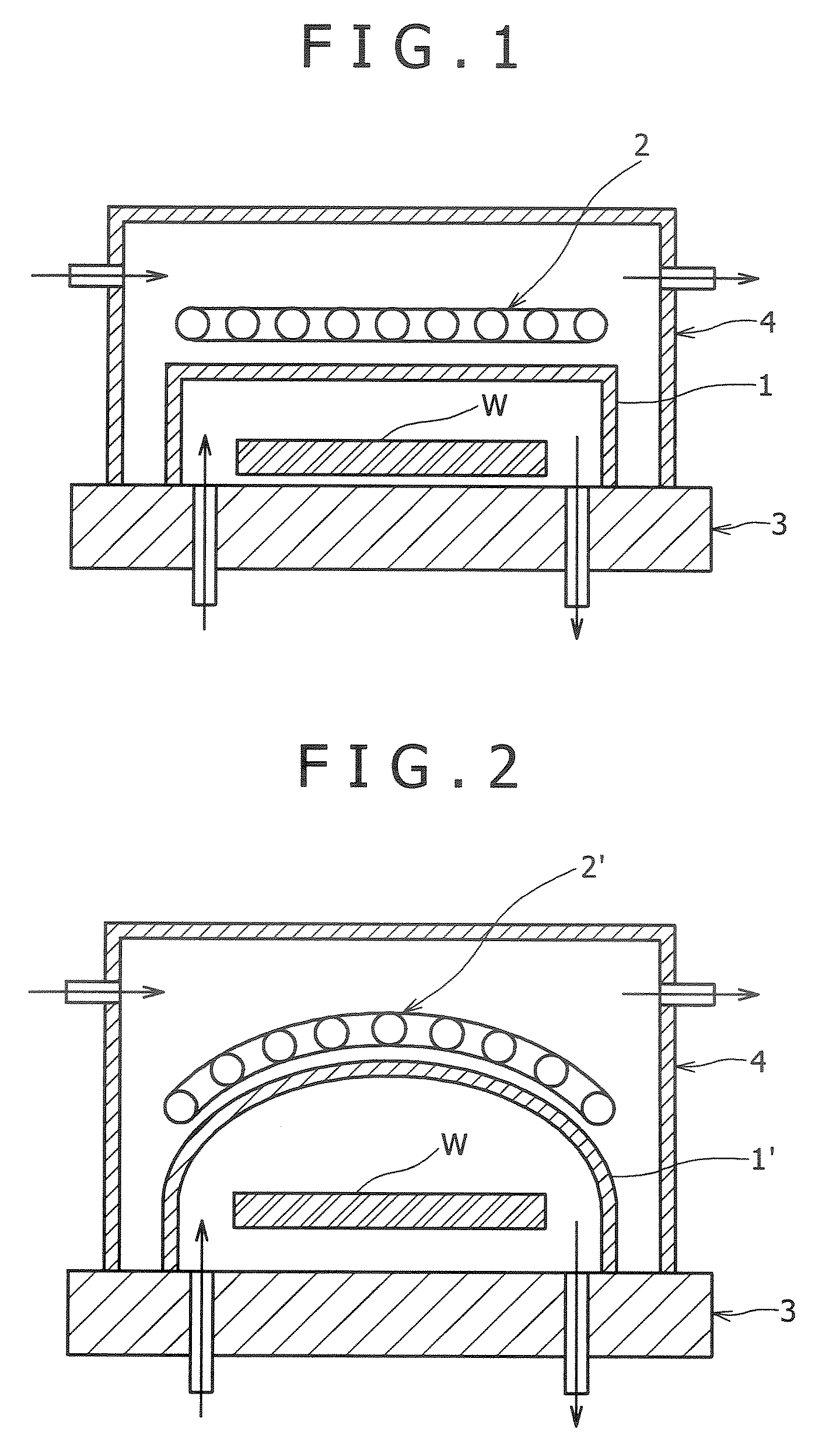
[0039]FIG. 1 is a sectional view schematically illustrating the structure of a heating apparatus according to a preferred embodiment of the present invention, and FIG. 2 is a sectional view schematically illustrating the structure of a heating apparatus according to another preferred embodiment of the present invention.

[0040] Referring to FIG. 1, reference numeral 1 indicates a dome-shaped heating container which has the inner diameter greater than the length of the container, is formed in the sectional shape of a circle, and is entirely made of glasslike carbon. In the container 1 is received an object W to be heated which has a large area and is formed into a shape of a substrate (a plate) such as a silicon wafer. Reference numeral 2 indicates a high-frequency plate-shaped coil disposed at the outside of the container 1. The coil is adjacent and is opposed to a flat-shaped ceiling part of the container 1, and is wound approximately into a shape of a plate. Consequently, the ceili...

examples 3 to 7

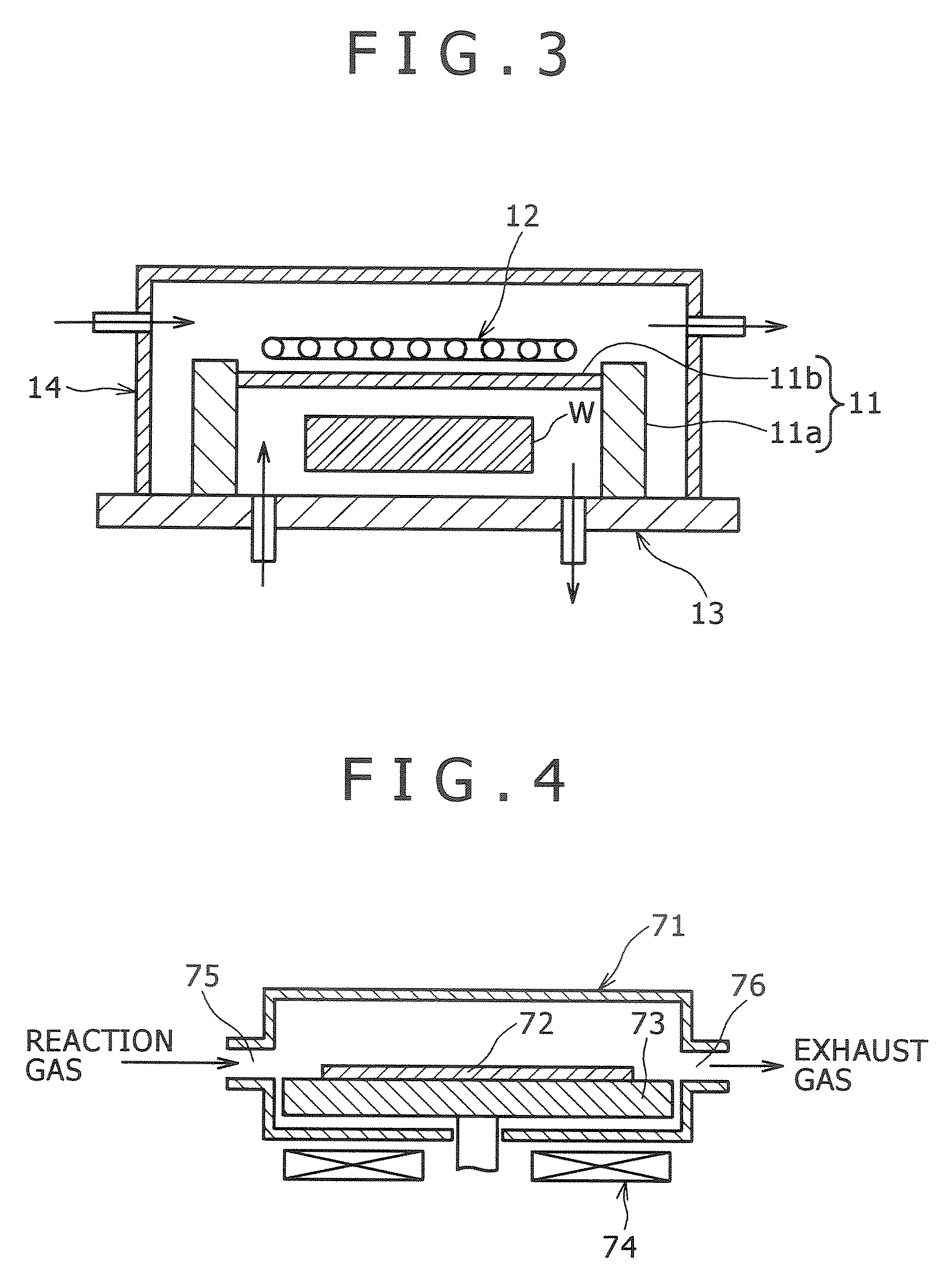
[0049]FIG. 3 is a sectional view schematically illustrating the structure of a heating apparatus according to yet another preferred embodiment of the present invention.

[0050] Referring to FIG. 3, reference numeral 11 indicates a dome-shaped heating container. The container 11 comprises a cylindrical body 11a of which the inner diameter is greater than the length of the cylindrical body 11a and is made of SUS316, in this example, and a circular heat generating plate (heat generating part) 11b made of glasslike carbon. The glasslike carbon heat generating plate 11b is attached to the open end of the ceiling side of the cylindrical body 11a via an O-ring for maintaining airtightness. The cylindrical body 11a has a length of 50 mm and an inner diameter of 400 mm. The heat generating plate 11b has an outer diameter of 400 mm and a thickness of 3.4 mm.

[0051] Reference numeral 12 indicates a high-frequency plate-shaped coil disposed at the outside of the container 11 while the coil 12 is...


PUM


Abstract

Disclosed herein is a heating apparatus designed to heat an object to be heated through induction heat generation of a heat generating part made of glasslike carbon, and that can rapidly raise or lower the temperature without contamination of the object which has a large area and is formed into a shape of a substrate such as a silicon wafer. The heating apparatus includes a heating container for receiving the object. The container is constructed such that at least a portion of the container formed into a shape of a plate is made of glasslike carbon, and that the portion of the container serves as a heat generating part. A high-frequency plate-shaped coil is disposed at the outside of the container while the coil is adjacent and is opposed to the heat generating part of the container, and which is wound approximately into a shape of a plate. The heating apparatus further includes a container-inside gas atmosphere control means for controlling the inside of the container to be maintained at a predetermined gas atmosphere. When electric current is supplied to the coil, heat is generated from the heat generating part through induction heat generation of the heat generating part, whereby the object is heated.

Description

BACKGROUND OF THE INVENTION [0001] 1. Field of the Invention [0002] The present invention relates to a heating apparatus used for heat treatment in the process for manufacturing a semiconductor integrated circuit. In particular, this invention relates to the heating apparatus that is designed to heat an object to be heated through induction heat generation of a heat generating part made of glasslike carbon and that can rapidly raise or lower the temperature without contamination of the object which has a large area and is formed into a shape of a substrate such as a silicon wafer. [0003] 2. Description of the Related Art [0004] In order to heat an object to be heated disposed in a predetermined gas atmosphere, there is generally used a combination comprising at least two components, i.e., a heating container which receives the object and maintains the interior of the container to the above-mentioned gas atmosphere, and a heating means for heating the object as well as the container....

Claims


Application Information

Patent Timeline
IPC IPC(8): H05B6/26H05B6/10
CPCH05B6/26
Inventor HAMAGUCHI, MAKI
Owner KOBE STEEL LTD
Learn More