
Sensor and Package Assembly Thereof

a technology of micro electromechanical technology and sensor, applied in the direction of microstructural devices, fluid speed measurement, instruments, etc., can solve the problems of increasing the number of elements and functions, and the difficulty of existing package solutions to meet the requirements of devices with a higher component density, etc., to achieve better heat distribution, volume and cost of the entire package assembly, and improve the structural support

Pending Publication Date: 2022-01-13
ROBERT BOSCH GMBH
View PDF0 Cites 0 Cited by
  • Summary
  • Abstract
  • Description
  • Claims
  • Application Information

AI Technical Summary

Benefits of technology

This patent describes a way to make a sensor package that can hold more elements and provide better support and heat distribution. This helps reduce the size and cost of the entire package.

Problems solved by technology

However, for current market demands, more elements and functions are required to be integrated into an increasingly small space.
It is difficult for existing package solutions to meet requirements for a device with a higher component density.

Method used


Image

  • Sensor and Package Assembly Thereof

Examples


Embodiment Construction

[0023]Embodiments of the present utility model are described in detail below in conjunction with the accompanying drawings.

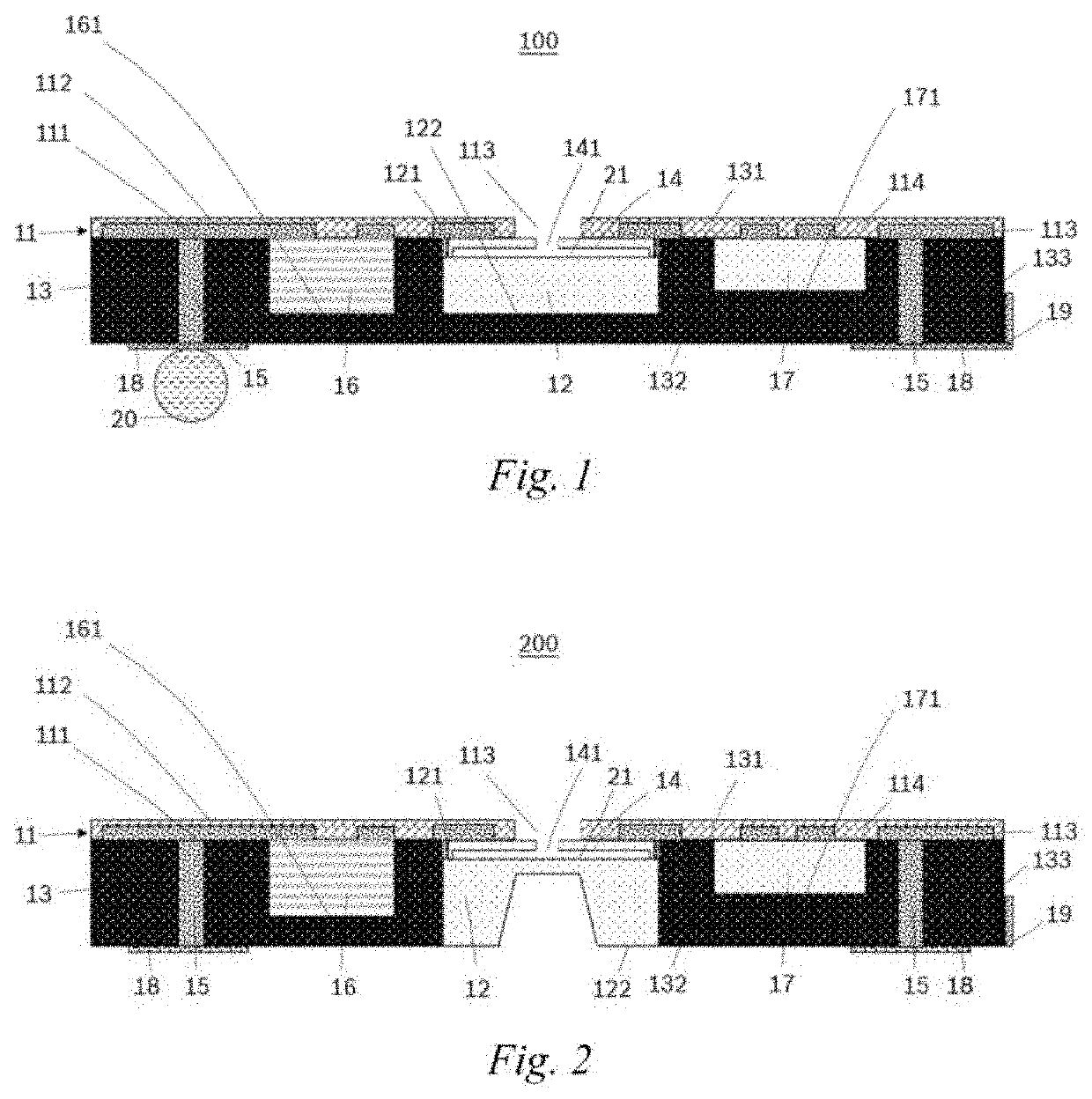
[0024]FIG. 1 shows a cross-sectional structure of a package assembly 100 of a sensor according to one embodiment of the present utility model. As shown in the figure, the package assembly 100 of the sensor comprises a redistribution layer (RDL) 11, a sensing element 12, a moulding compound 13, a cover body 14, and a first die 16. Optionally, the package assembly of the sensor further comprises a second die 17. The RDL 11 comprises a first face 111 and a second face 112 opposite to each other, and a first via 113 that penetrates the first face 111 and the second face 112. The sensing element 12, the first die 16, and the second die 17 are electrically connected to the first face 111 of the RDL 11. The moulding compound 13 encapsulates the sensing element 12, the first die 16, and the second die 17 on the side of the first face 111 of the RDL 11. The moulding comp...


PUM


Abstract

The present utility model discloses a package assembly of a sensor, comprising: a redistribution layer having a first face and a second face that are opposite to each other, and a first via that penetrates the first face and the second face; a first die electrically connected to the first face of the redistribution layer; a sensing element electrically connected to the first face of the redistribution layer; a cover body located between the redistribution layer and the sensing element, wherein the cover body has a second via that penetrates the cover body, and the second via communicates with the first via; and a moulding compound comprising a third face and a fourth face that are opposite to each other, wherein the moulding compound encapsulates the first die and the sensing element on the side of the first face of the redistribution layer, and the third face of the moulding compound is combined with the first face of the redistribution layer. The package assembly of the sensor allows more components to be packaged together, provides a better structural support and heat distribution, and reduces the volume and costs of the package assembly.

Description

TECHNICAL FIELD[0001]The present utility model relates to sensor technologies, and in particular to a sensor based on micro electro-mechanical technology, and a package assembly thereof.BACKGROUND ART[0002]A micro electro-mechanical system (MEMS) sensor is a sensor manufactured by using microelectronic and micromechanical processing techniques. Compared with conventional sensors, the MEMS sensor is characterized by a small volume, a light weight, low costs, low power consumption and high reliability, and is suitable for mass production and easy to integrate and achieve intelligentization. In addition, the feature size of the order of microns makes it possible for the MEMS sensor to complete certain functions that cannot be implemented by conventional mechanical sensors. MEMS sensors are widely applied to the fields of automobiles, portable consumer electronic devices, and even medical treatment.[0003]A package of the MEMS sensor is a key factor in design and manufacture of the MEMS ...

Claims


Application Information

Patent Timeline
Patent Type & Authority Applications(United States)
IPC IPC(8): B81B7/00
CPCB81B7/007B81B2207/098B81B2207/012B81B2201/0264B81C1/0023B81B7/0061B81B2207/096
Inventor CHANG, KENCHUANG, WALLACE
Owner ROBERT BOSCH GMBH
Learn More