
Self-sealing vascular graft

a vascular graft and self-sealing technology, which is applied in the field of self-sealing vascular grafts, can solve the problems of grafts not being reliable long-term patency solutions, the risk of undermining the veins of patients, and the leakage of punctures in such tubing under the pressure of the circulatory system, so as to improve the leakage resistance of the access element, and improve the leakage resistan

Active Publication Date: 2007-05-31
VASCULAR DEVICES
View PDF61 Cites 24 Cited by
  • Summary
  • Abstract
  • Description
  • Claims
  • Application Information

AI Technical Summary

Benefits of technology

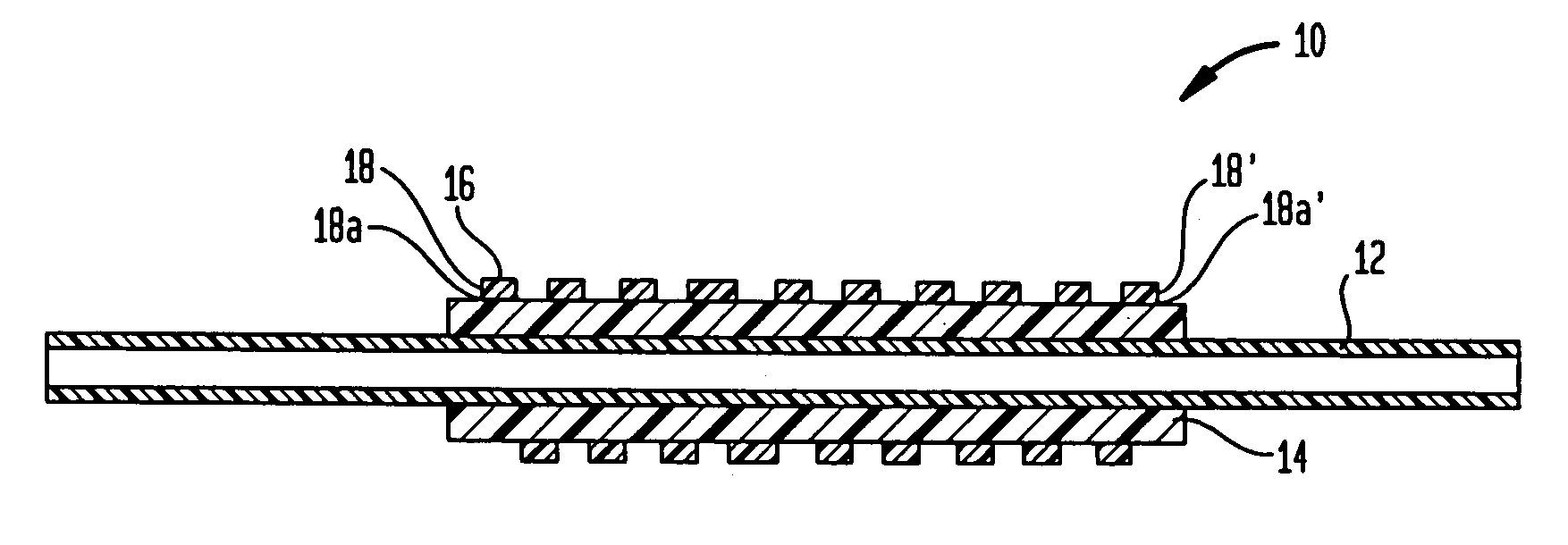
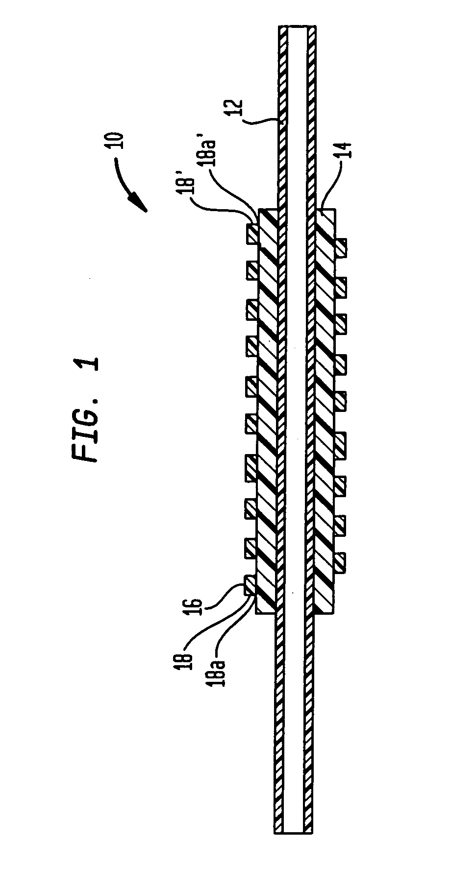
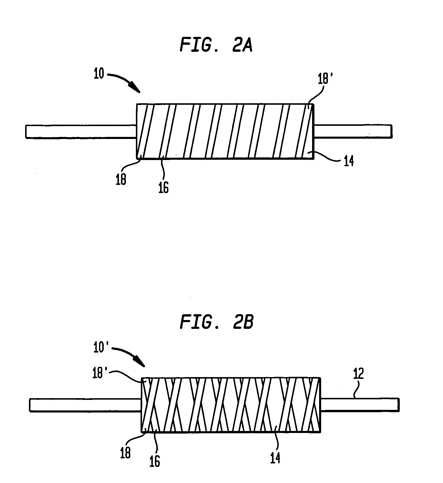
"The present invention provides an artificial graft that includes a base tubing element, a tubular access element, and a compression element. The compression element is formed over the access element and provides radial inward compression to improve its leakage resistance after being punctured. The compression element can be a strand-like compression element or a biocompatible silicone layer. The graft is made of a tubular base element, an overlying sleeve-like access element, and a compression member, which can be a strand-like compression element, a biocompatible silicone layer, or a spiral or helical band. The graft is smoothly surgical tunneling and stable during use. The technical effects of the invention are improved leakage resistance and stability of the graft during use."

Problems solved by technology

With the frequency of dialysis treatments, puncture wounds accumulate, and there is a danger of undermining the patient's veins.
However, the punctures in such tubing tend to leak under the pressure of the circulatory system.
Efforts have been made to use tubes made of a self-sealing polymer or to provide a multilayered structure to resolve these problems; but such grafts have not been proven to be a reliable solution to long term patency.

Method used


Image

  • Self-sealing vascular graft
  • Self-sealing vascular graft
  • Self-sealing vascular graft

Examples


third embodiment

[0025]FIG. 3 illustrates an artificial graft 20 in accordance with the present invention. This embodiment is similar to embodiments 10 and 10′ in FIGS. 1, 2A and 2B except that an outer covering 22 is provided over compression element 16 in the structures. In FIG. 3, those elements which are identical to elements in FIG. 1 have been indicated with the same reference numbers.

[0026] Preferably, the covering 22 is made of platinum-cured silicone gum or a liquid silicone with a durometer hardness of 20-35 Shore A (NuSil MED-4035 or equivalent). This material is compression molded on the structure after compression element 16 has been secured, in a manner similar to access element 14. In the preferred embodiment, covering 22 has a wall thickness of about 0.25 to about 0.5 mm. It is also preferred that cover 22 have an exterior surface #45 “texturing”(Charmilles Technologies, VDI 3400), or a micro-porosity (50 to 200 microns) providing an environment to allow for biological connective mat...

fourth embodiment

[0027]FIG. 4 illustrates an artificial graft 30 in accordance with the present invention. Graft 40 broadly comprises a base tubing element 12, a tubular access element 14 overlying the base tubing, and an outer covering 32 formed over access element 14 so as to provide radial compression to the access element. In the embodiment illustrated, the covering 32 may extend past the extent of the access element 14 and about a portion of the tubing element.

[0028] Base tubing element 12 preferably has a circular cross-section but it may have any cross-sectional shape commonly used for surgical and implantation applications. Tubing element 12 is preferably made of implant grade ePTFE tubing having an inside diameter about 6.0 mm and a wall thickness of about 0.5 mm. Preferably the graft 30 is provided in a fixed length, usually longer then required and cut by surgeon, for example to the length of base tubing element 12, which is convenient for implantation, for example about 30 cm. However tu...


PUM


Abstract

The present invention relates to a segmental self-sealing graft for implantation in a patient including a base tubing element, a tubular access element overlying the base tubing, and a strand-like compression element wound over the access element so as to provide radially inward compression, and a method of making same.

Description

CROSS-REFERENCE TO RELATED APPLICATIONS [0001] This application claims the benefit of the filing date of U. S. Provisional Patent Application No. 60 / 736,385 filed Nov. 14, 2005, the disclosure of which is hereby incorporated herein by reference.BACKGROUND OF THE INVENTION [0002] Grafts, for example hemodialysis grafts, are often used for patients who need to receive frequent injections, blood filtration, or vascular access procedures. For example, patients who receive kidney dialysis typically received several treatments per week. In order for the patient to receive treatment, the patient's skin must be punctured with a hemodialysis needle. Such needles are typically about 15-17 gauge, and they leave a puncture which takes some time to heal. With the frequency of dialysis treatments, puncture wounds accumulate, and there is a danger of undermining the patient's veins. [0003] It has become common to implant a graft in the patient's arm to receive the punctures. Typically, the graft i...

Claims


Application Information

Patent Timeline
Patent Type & Authority Applications(United States)
IPC IPC(8): A61F2/06
CPCA61M39/0208A61M2039/0072
Inventor WEINBERG, STEVEN
Owner VASCULAR DEVICES
Learn More