
Robotic total/partial knee arthroplastics

a robotic system and knee joint technology, applied in the field of robotic total/partial knee arthroplasty, can solve the problems of inaccurate estimation, premature failure of the repaired joint, and inability to perform the measurement of the mechanical axis of the leg intraoperatively, so as to relieve the onus of measurement and increase the accuracy of tkr/tka/uni

Active Publication Date: 2007-05-03
MAZOR ROBOTICS
View PDF21 Cites 189 Cited by
  • Summary
  • Abstract
  • Description
  • Claims
  • Application Information

AI Technical Summary

Benefits of technology

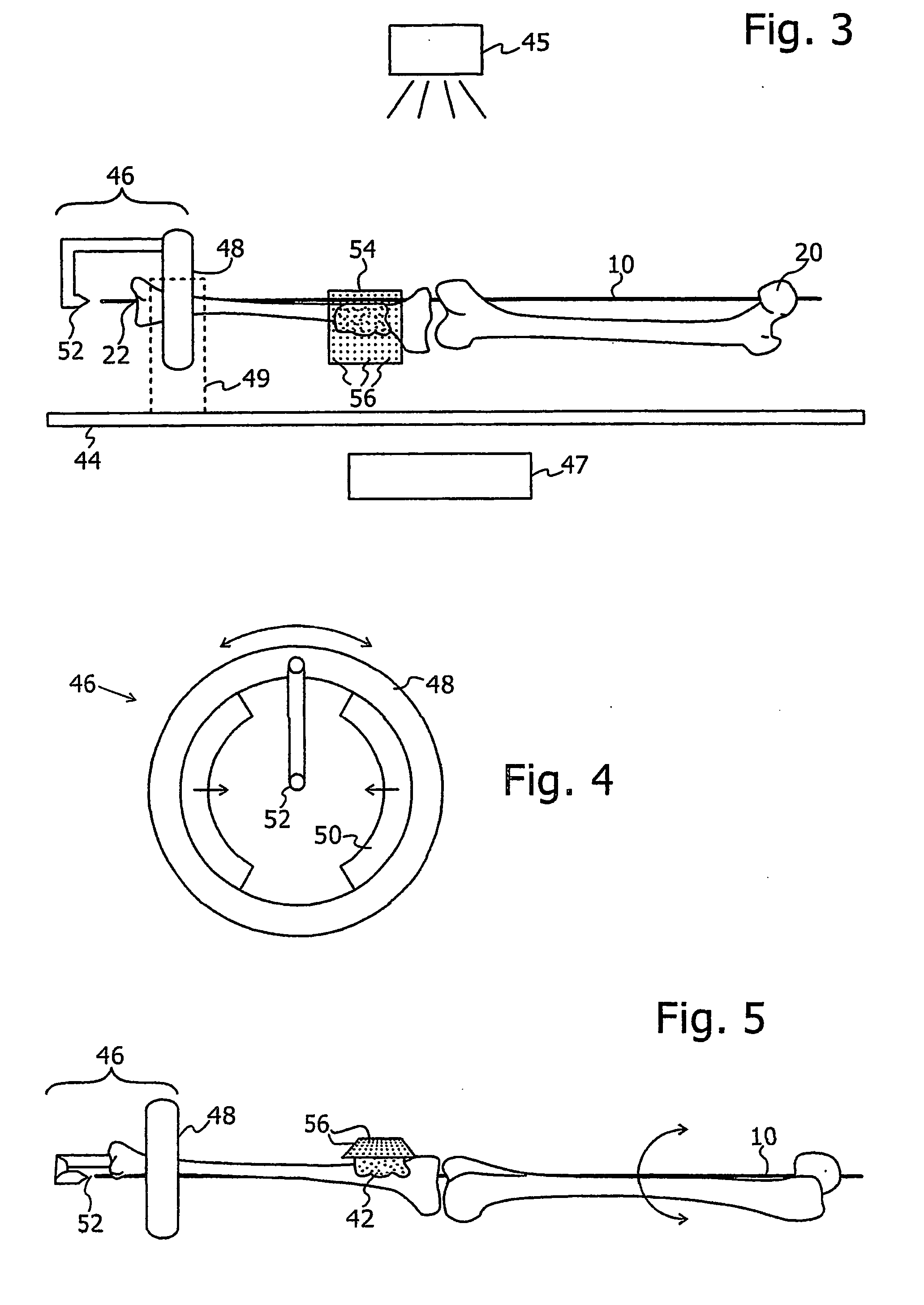
[0018] The present invention seeks to provide a new system, method and associated accessories, which enable an increase in the accuracy of TKR / TKA / UNI procedures to be achieved, and, by the use of automating the procedure, relieves the onus of the measurements from the surgeon, without the need for the addition of a complex and costly navigation system. The system and procedure of the present invention allows for optimum implant positioning. The system preferably uses a robotic system to define the cutting planes, and an adjustable leg rotation fixture to determine of the mechanical axis of the leg. The novel adjustable leg rotation fixture of the present invention can also be used advantageously in the standard manual cut operations, where conventional cut guidance jigs are used instead of a robot.
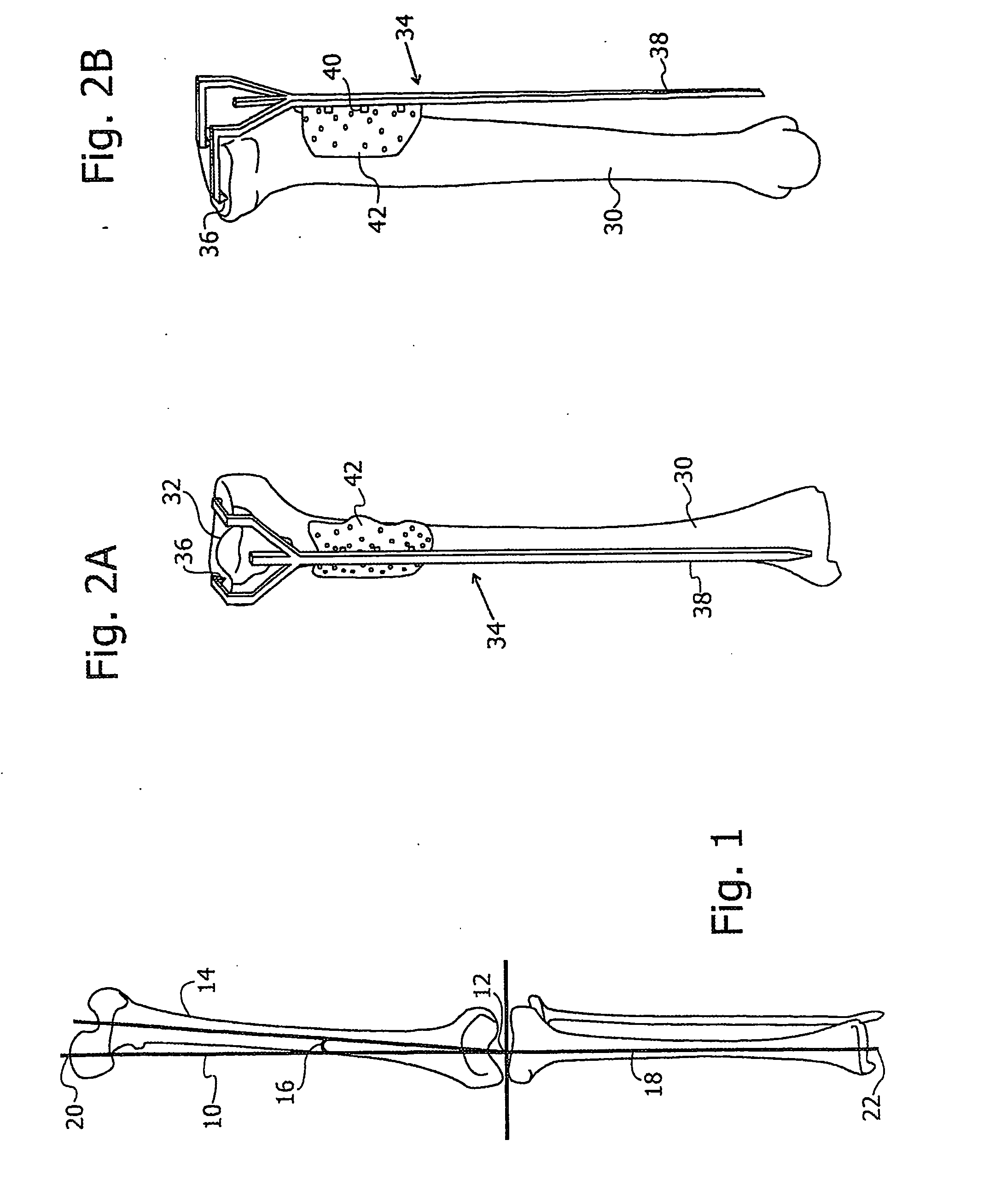
[0022] Once the tibia cut has been performed, the femur cut has to be performed at the correct orientation and at the correct distance from the tibia cut. This position can be obtained using the system of the present invention, according to a first preferred embodiment, by providing an additional degree of freedom to the above-described leg rotation fixture of the present invention, to enable the leg to perform a rotation in the plane of the operating table, thus enabling by means of at least one further C-arm X-ray image, to determine the coordinates of the center of the femur head at the center of rotation of the leg axis. According to a second preferred method, a target rod is attached in a known position onto the base plate, and extending from the knee region along the femur. Its presence in a further C-arm image taken at the pelvic region, enables the femur mechanical axis to be defined, since the center of the femur head can be obtained by image processing of the top of the femur, and the presence of the target rod in this image enables the position of the base plate to be related thereto, and the position of the base plate is known relative to the C-arm coordinate system. Once the femur mechanical axis is known in addition to the leg mechanical axis in the C-arm coordinate system, the robot can be used to define the position of the femur cut, in a similar way to that performed for the tibia cut. The system allows choice of the cut angle and distance relative to the tibia cut.
[0023] The system and its associated accessories thus enables both the tibia and femur cuts to be achieved with robotic accuracy, at positions and orientations chosen by the surgeon to match the availability of implant sizes.
[0024] The potential advantages engendered by the use of the system of the present invention, over currently used procedures, include: (1) Improved accuracy of the procedure, resulting from accurate guidance for the surgeon and reliable measurements and instrumentation. (2) Minimal invasiveness of procedure due to accurate instrumentation guidance. (3) Simplification of the work flow of the entire procedure. (4) Enabling the surgeon to easily modify the cutting planes of the bones. (5) Shortening of the procedure time. (6) Fewer surgical instruments required for the procedure. (7) Decreased bone damage.
[0025] Additionally, the system allows the surgeon: (8) To choose the bone cutting planes in relation to the mechanical axis of the leg, which cannot be measured and related to intraoperatively using prior art procedures. (9) To perform the cuts accurately by use of robot-held jigs that guide the surgical tools, or by allowing the robot to perform the cut directly.
[0026] (10) To have a high degree of flexibility for jig relocation, if mandated by an intraoperative decision of the surgeon, which is not available in prior art procedures, where a change in decision about the cutting plane involves relocation of the cutting jig on the bone.

Problems solved by technology

With prior art techniques as currently used, measurements of the leg mechanical axis are not performed intraoperatively.
This task is problematic because of the difficulty of accurately estimating the orientation of the cutting planes, each having two rotational degrees of freedom, relative to the leg's mechanical axis, the tibia axis and the femur axis, and one translational degree of freedom relative to the bone positions, in a situation when almost all of the leg structure is covered by soft tissue and no axis measurements are performed.
61-66, 2003, over one third of such operations were found to have deviations from ideal prosthesis alignment which resulted in premature failure of the repaired joint.
According to other studies, it is believed that the failure rate of such knee joint operations, as defined by the need for a corrective operation within 2 years, is up to 15% of the total number performed, half of which are due to misalignment problems.
Because of the complexity of the situation produced, a corrective operation is often several times more costly than a regular operation.
The main drawback of such systems is their complexity, the longer procedure time required, their price and their large size, all or some of which may be contributory factors as to why there has so far been small usage of such systems in these procedures, when compared to the use of conventional TKA tools.

Method used


Image

  • Robotic total/partial knee arthroplastics
  • Robotic total/partial knee arthroplastics
  • Robotic total/partial knee arthroplastics

Examples


Embodiment Construction

[0064] Reference is now made to FIG. 1, which illustrates schematically an anterior / posterior (A / P) view of the bones of a leg, showing the various axes of the leg components in their correct anatomical positions, as used by the system and methods of the present invention in the execution of the surgical procedures enabled thereby. The details of the parts of FIG. 1 have been described hereinabove in the Background to the Invention section of this application.

[0065] As a first step, the surgeon performs the conventional antero-lateral or antero-medial skin incision of the knee. He then makes a cut along the Retinaculum pattelae mediale in order to move aside the patella and to expose the entire structure of the knee joint, including the top end of the tibia, the bottom end of the femur, the meniscus, ligaments, etc., as is known in routine orthopedic surgical procedures on the knee. Standard surgical instruments are used to pull aside the patella together with the Retinaculum patte...


PUM


Abstract

A system and method for knee arthroplasty procedures, using a novel leg rotation fixture to enable the leg mechanical axis, the tibia and the femur to be mutually disposed such that the load bearing, mechanical axis of the leg runs through the center of the knee joint. A measurement gauge is provided for mounting on the tibia and for aligning a baseplate in a known position on the tibia. This baseplate supports an X-ray target plate in a known position relative to the tibia, used in determining the mechanical axis, and an optional surgical robot, used to perform tibial and femoral cuts. The position of the femur relative to the robot may be determined from X-ray imaging of the pelvic region after attachment to the baseplate of an additional target extending to the pelvic region. The system enables improvement in the accuracy of knee arthroplasty procedures.

Description

FIELD OF THE INVENTION [0001] The present invention relates to the field of the use of robotic systems in knee joint replacement operations, and especially for improving the accuracy of implant installation and their longevity using a novel orthopedic guidance system. BACKGROUND OF THE INVENTION [0002] The goals of the operative procedures known as total knee replacement, partial knee arthroplastic or the uni-condyler procedure (TKR / TKA / UNI) are to restore pain free walking capability in patients having worn or diseased knee joints. In these common orthopedic procedures, damaged surfaces of the knee bones are replaced with prosthetic joint implants, installed at the distal femoral and proximal tibial bone ends, after appropriate cuts of the tibia and femur bones have been made by the surgeon. In order to ensure correct functionality of the knee and a long working life of the implants, all of the implanted components must be positioned with high precision in relation to the mechanica...

Claims


Application Information

Patent Timeline
IPC IPC(8): A61F5/00A61BA61B5/05A61B17/15A61B17/17A61B19/00
CPCA61B6/0421A61B17/155A61B17/157A61B17/1703A61B17/1725A61B19/2203A61B2019/2226A61B2019/5238A61B17/1764A61B2090/376A61B34/30A61B2034/304
Inventor SHOHAM, MOSHEBURMAN, MICHAEL
Owner MAZOR ROBOTICS
Learn More