Eureka AIR delivers breakthrough ideas for toughest innovation challenges, trusted by R&D personnel around the world.

Soft magnetic film, method of manufacturing soft magnetic film, thin film magnetic head that uses soft magnetic film, and method of manufacturing thin film magnetic head

a soft magnetic film and manufacturing method technology, applied in the field thin film magnetic head, manufacturing method of soft magnetic film, can solve the problems of not being regarded as serious effects on soft magnetic characteristics, not being able to properly concentrate the magnetic flux on the end of main magnetic pole layer, and not being able to improve recording density, etc., to achieve the effect of higher saturation magnetic flux density

Inactive Publication Date: 2007-05-03
TDK CORPARATION +1
View PDF8 Cites 4 Cited by
  • Summary
  • Abstract
  • Description
  • Claims
  • Application Information

AI Technical Summary

Benefits of technology

[0016] In one embodiment, a soft magnetic film is plated with Fe and Ni, Fe and Co, or Fe, Ni and Co. In this embodiment, a ratio Cl / Fe of ion strengths between negative-charged Fe and Cl and a ratio S / Fe of ion strengths between negative-charged Fe and S are less than 10 in measurement by a time-of-flight secondary ion mass spectrometry (hereinafter, referred to as a TOF-SIMS). It is possible to obtain a higher saturation magnetic flux density with the coercive force being maintained to be low.
[0017] In the above-mentioned embodiment, it is preferable that the ratio Cl / Fe is 2 or less. Accordingly, it is possible to obtain a higher saturation magnetic flux density.
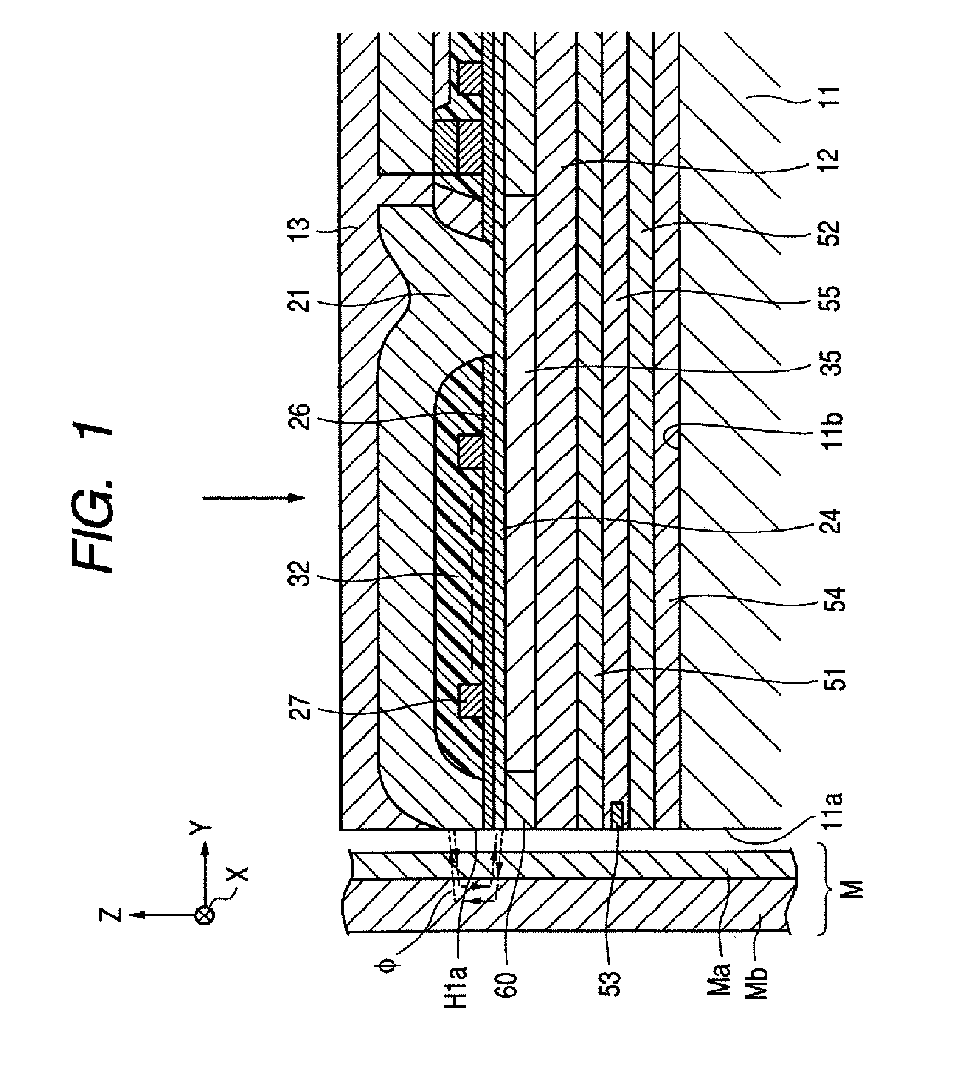
[0018] In another embodiment, a thin film magnetic head includes a main magnetic pole layer that has a track width on a surface that faces a recording medium. A sub magnetic pole layer has a width wider than the main magnetic pole layer so as to face the main magnetic pole layer in a film thickness direction. A coil layer applies a recording magnetic field to the main and sub magnetic pole layers. In this embodiment, magnetic data is recorded on the recording medium by a perpendicular magnetic field concentrated on the main magnetic pole layer. At least the main magnetic pole layer is plated with the above-mentioned soft magnetic film. Accordingly, since the main magnetic pole layer has high saturation magnetic flux density and low coercive force, it has high recording density and residual magnetization is suppressed. It is possible to efficiently prevent recording signals from being eliminated due to the residual magnetization.
[0021] In the above-mentioned method, it is preferable that boric acid be contained in the plating bath until the boric acid is saturated in the plating bath. Chloride such as NaCl is used to enhance the conductivity of the plating bath is not contained in the bath. The resistance of plating bath increases, causing uniform electrodeposition performance to be deteriorated. Accordingly, it is possible to enhance the uniform electrodeposition performance by adding boric acid close to its saturation concentration in the plating bath in order to suppress variation in pH of the plating bath.
[0023] It is possible to easily and appropriately plate the main magnetic pole layer with a magnetic layer that has a higher saturation magnetic flux density with the coercive force maintained to be low.

Problems solved by technology

At a low saturation magnetic flux density Bs, an end of main magnetic pole layer is apt to reach magnetic saturation, such that it is not possible to properly concentrate the magnetic flux on the end of main magnetic pole layer.
Thus, it is not possible to improve the recording density.
However, a very small amount (i.e. in ppm units) of impurities is injected into the soft magnetic film, which is not regarded to have a serious effect on soft magnetic characteristics.
Further, impurities such as Cl have not been particularly controlled until now.
The resistance of plating bath increases, causing uniform electrodeposition performance to be deteriorated.

Method used


Image

  • Soft magnetic film, method of manufacturing soft magnetic film, thin film magnetic head that uses soft magnetic film, and method of manufacturing thin film magnetic head
  • Soft magnetic film, method of manufacturing soft magnetic film, thin film magnetic head that uses soft magnetic film, and method of manufacturing thin film magnetic head
  • Soft magnetic film, method of manufacturing soft magnetic film, thin film magnetic head that uses soft magnetic film, and method of manufacturing thin film magnetic head

Examples


examples

(Soft Magnetic Film of Examples)

[0080] A plurality of FeCoNi alloys that have different composition ratios is plated using the following plating bath.

[0081] (Composition of Plating Bath)

FeSO4•7H2O5.6 to 14(g / l)CoSO4•7H2O0.6 to 4.6(g / l)NiSO4•6H2O4 to 12(g / l)H3BO330(g / l)Malonic acid0.02(g / l)NaCl0(g / l)Sodium Lauryl Sulfate0(g / l)

[0082] (Bath Conditions)

Bath temperature30° C.pH3.1 to 3.2Current density of pulse current (high) (peak)20 mA / cm2Current density of pulse current (low) (peak)5.5 mA / cm2Duty ratio0.15

[0083] A plurality of FeCoNi alloys shown in the following Table 1 was obtained from the plating bath that uses modulation pulses that have the current densities.

TABLE 1CoerciveCoerciveSaturationForceForceAnisotropicMagnetic(easy-(hard-MagneticFluxaxis)axis)FieldDensityFeCoNiHc(E.A)Hc(H.A)HkBsExample[wt %][wt %][wt %][Oe][Oe][Oe][T]10.259.5420.211.040.859.751.9973.038.5118.461.500.806.202.0174.948.1016.961.600.288.202.0276.717.7815.521.400.606.152.0577.107.2015.701.680.655.3...


PUM

PropertyMeasurementUnit
Temperatureaaaaaaaaaa
Fractionaaaaaaaaaa
Fractionaaaaaaaaaa

Abstract

A soft magnetic film and a method of manufacturing the soft magnetic film are provided. The soft magnetic film is plated with Fe and Ni, Fe and Co, or Fe, Ni and Co. A ratio Cl / Fe of ion strengths between negative-charged Fe and Cl and a ratio S / Fe of ion strengths between negative-charged Fe and S are less than about 10 in measurement by a time-of-flight secondary ion mass spectrometry.

Description

[0001] This patent document claims the benefit of Japanese Patent Application 2005-312433 filed on Oct. 27, 2005 which is hereby incorporated by reference. BACKGROUND [0002] 1. Field [0003] The present embodiments relate to a soft magnetic film, a method of manufacturing the soft magnetic film, a thin film magnetic head that uses the soft magnetic film, and a method of manufacturing the thin film magnetic head. [0004] 2. Related Art [0005] A perpendicular magnetic recording method is used in an apparatus for recoding magnetic data with high density on a recording medium such as a hard disk. The perpendicular magnetic recording method is advantageous in terms of high recording density more than a longitudinal magnetic recording method. [0006] A magnetic head used in the perpendicular magnetic recording method generally includes a main magnetic pole layer and a sub magnetic pole layer (return yoke) that face each other in a film thickness direction on a surface that faces a recording ...

Claims


Application Information

Patent Timeline
IPC IPC(8): G11B5/147G11B5/127
CPCY10T29/49021G11B5/1278
Inventor YAZAWA, HISAYUKITAKAHASHI, SHIO
Owner TDK CORPARATION
Why Eureka
Eureka Blog
Learn More