Soft magnetic under layer
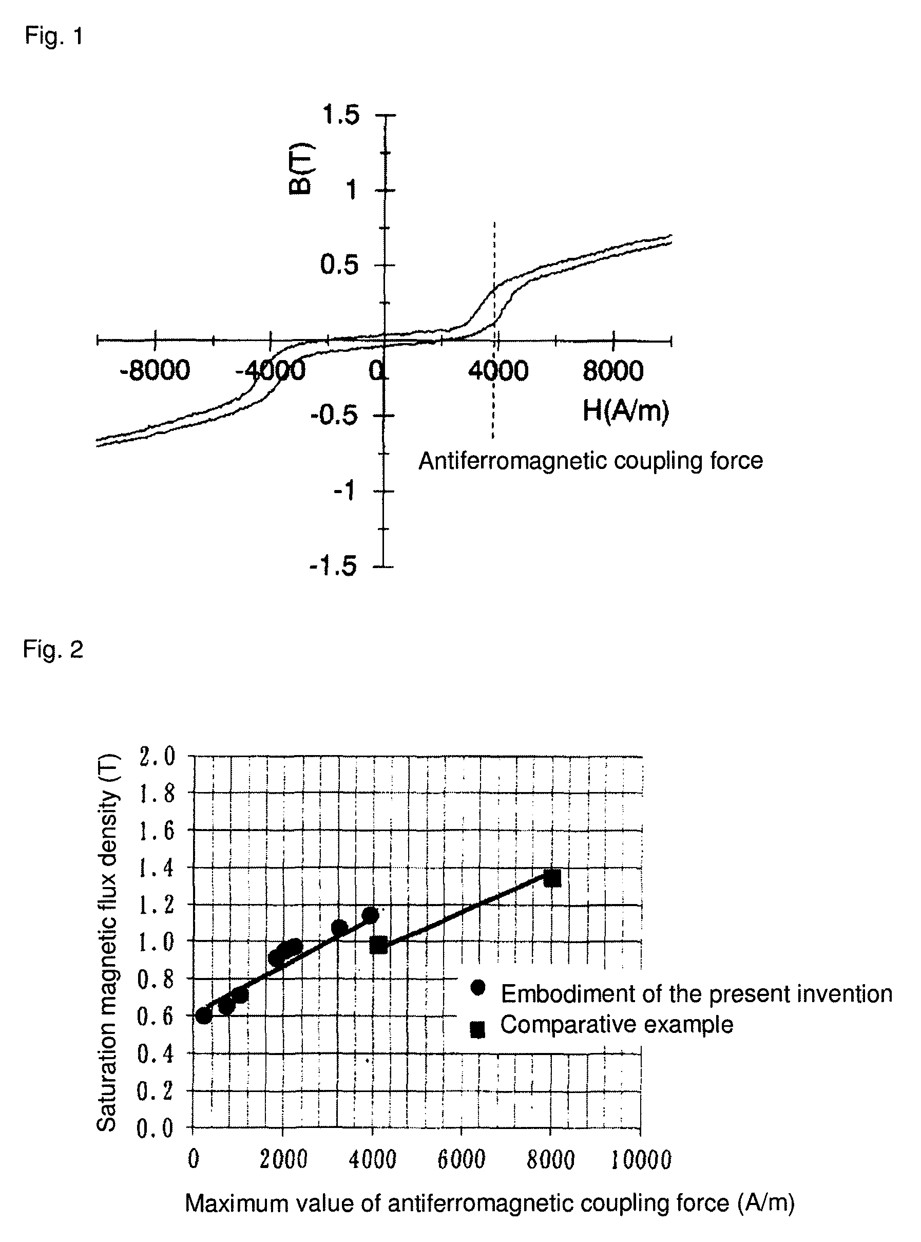
a soft magnetic and layer technology, applied in the field of soft magnetic under layer, can solve the problems of increasing the flying height of the magnetic head and deteriorating reproducing sensitivity, and achieve the effects of low antiferromagnetic coupling force, high saturation magnetic flux density, and effective technology
- Summary
- Abstract
- Description
- Claims
- Application Information
AI Technical Summary
Benefits of technology
Problems solved by technology
Method used
Image
Examples
embodiment 1
of the Present Invention
[0043]In order to prepare an Fe—Co alloy target for forming a soft magnetic layer, gas atomized powders each having a purity of 99.9% or greater and having alloy compositions of Fe92—Ta8 (atomic %), Fe90—Zr10 (atomic %), Fe70—B30 (atomic %), Co62.3—Fe26.7—Ta3—Zr5—Ti3 (atomic %), and Co88—Ta10—Zr2 (atomic %); and a Ti powder having a purity of 99.9% or greater were prepared. The powders were weighed and mixed to produce a mixed powder having an alloy composition of (Fe80—Co20)85—Ta3—Zr5—Ti3—B4 by atomic ratio. Subsequently, the produced mixed powder was filled in a soft steel capsule, and then degassed and sealed. Then, the mixed powder was sintered by hot isostatic pressing at a temperature of 950° C., a pressure of 122 MPa, and a hold time of two hours to produce a sintered body. The produced sintered body was machined to produce an Fe—Co alloy target having a diameter of 180 mm and a thickness of 4.0 mm.
[0044]In order to prepare a Ru target for forming a sp...
embodiment 2
of the Present Invention
[0048]In order to prepare an Fe—Co alloy target for forming a soft magnetic layer, gas atomized powders each having a purity of 99.9% or greater and having alloy compositions of Fe92—Ta8 (atomic %), Fe90—Zr10 (atomic %), Fe70—B30 (atomic %), Co62.3—Fe26.7—Ta3—Zr5—Ti3 (atomic %), and Co88—Ta10—Zr2 (atomic %); and a Ti powder having a purity of 99.9% or greater were prepared. The powders were weighed and mixed to produce a mixed powder having an alloy composition of (Fe90—Co10)86—Ta3—Zr5—Ti2—B4 by atomic ratio.
[0049]The produced mixed powder was filled in a soft steel capsule, and then degassed and sealed. Then, the mixed powder was sintered by hot isostatic pressing at a temperature of 950° C., a pressure of 122 MPa, and a hold time of two hours to produce a sintered body. The produced sintered body was machined to produce an Fe—Co alloy target having a diameter of 180 mm and a thickness of 4.0 mm.
[0050]Using the Fe—Co alloy target and Ru target produced above...
embodiment 3
of the Present Invention
[0051]In order to prepare an Fe—Co alloy target for forming a soft magnetic layer, gas atomized powders each having a purity of 99.9% or greater and having alloy compositions of Fe92—Ta8 (atomic %), Fe90—Zr10 (atomic %), Fe70—B30 (atomic %), Co, and Co88—Ta10—Zr2 (atomic %); and a Cr powder having a purity of 99.9% or greater were prepared. The powders were weighed and mixed to produce a mixed powder having an alloy composition of (Fe80—Co20)82—Ta3—Zr5—Cr6—B4 by atomic ratio.
[0052]The produced mixed powder was filled in a soft steel capsule, and then degassed and sealed. Then, the mixed powder was sintered by hot isostatic pressing at a temperature of 950° C., a pressure of 122 MPa, and a hold time of two hours to produce a sintered body. The produced sintered body was machined to produce an Fe—Co alloy target having a diameter of 180 mm and a thickness of 4.0 mm.
[0053]Using the Fe—Co alloy target and Ru target produced above, specimens for X-ray diffraction ...
PUM
| Property | Measurement | Unit |
|---|---|---|
| thickness | aaaaa | aaaaa |
| thickness | aaaaa | aaaaa |
| thickness | aaaaa | aaaaa |
Abstract
Description
Claims
Application Information
 - R&D
- Intellectual Property
- Life Sciences
- Materials
- Tech Scout
- Unparalleled Data Quality
- Higher Quality Content
- 60% Fewer Hallucinations
Browse by: Latest US Patents, China's latest patents, Technical Efficacy Thesaurus, Application Domain, Technology Topic, Popular Technical Reports.
© 2025 PatSnap. All rights reserved.Legal|Privacy policy|Modern Slavery Act Transparency Statement|Sitemap|About US| Contact US: help@patsnap.com


