Eureka AIR delivers breakthrough ideas for toughest innovation challenges, trusted by R&D personnel around the world.

Transparent electrode for solar cells, manufacturing method thereof, and semiconductor electrode comprising the same

a technology of solar cells and semiconductor electrodes, which is applied in the manufacture of final products, sustainable manufacturing/processing, electrolytic capacitors, etc., can solve the problems of impeded electron migration, high manufacturing cost, and only limited improvement in energy conversion efficiency, and achieve low electrical resistance characteristics, good uv blocking performance, and high transmittance.

Inactive Publication Date: 2007-05-03
SAMSUNG ELECTRONICS CO LTD
View PDF3 Cites 47 Cited by
  • Summary
  • Abstract
  • Description
  • Claims
  • Application Information

AI Technical Summary

Benefits of technology

[0010] Accordingly, the present invention provides a transparent electrode for solar cells, which has high transmittance and low electrical resistance characteristics while providing a good UV-blocking performance that reduces the deterioration of the dye and the electrolyte. This improves the solar cell and extends the life cycle of the solar cell.
[0011] The present invention further provides a method for manufacturing a transparent electrode for solar cells, which can be used to manufacture the transparent electrode inexpensively via a simple process.

Problems solved by technology

Monocrystalline, polycrystalline or amorphous silicon solar cells have mainly been used, but these have high manufacturing costs and display only limited improvement with respect to energy conversion efficiency.
However, the indium tin oxide electrode has problems in that it impedes the migration of electrons due to its high electrical resistance, and thus cannot provide a uniform electrical current when used in large-area applications.
It is also manufactured at a high cost through a relatively complex process.
However, since the mesh pattern is formed through a photoresist or etching process, the manufacturing process thereof is complex, which increases manufacturing costs.

Method used


Image

  • Transparent electrode for solar cells, manufacturing method thereof, and semiconductor electrode comprising the same
  • Transparent electrode for solar cells, manufacturing method thereof, and semiconductor electrode comprising the same
  • Transparent electrode for solar cells, manufacturing method thereof, and semiconductor electrode comprising the same

Examples


example 1

[0067] An isopropanol solution of polybutyl titanate (5.0 wt %) was applied on a transparent polyethylene sulfone (PES) by spin coating at 2000 revolutions per minute (rpm) and dried on a hot plate at 100° C. for 3 minutes, thus forming a photocatalytic layer having a thickness of about 50 nm. 10 grams (g) of polyvinyl alcohol (a molecular weight of 6000), 12 g of citric acid, 1.0 ml of triethanolamine and 15 ml of isopropyl alcohol were dissolved in 200 ml of distilled water, and the solution was spin-coated on the photocatalytic layer at 2000 rpm and dried on a hot plate at 100° C. for 5 minutes, thus forming a water-soluble polymer layer having a thickness of about 200 nm. The resulting substrate having the photocatalytic layer formed thereon was irradiated with 500 W of ultraviolet light having a broad wavelength range by means of a UV exposure system (Oriel Co. USA) through a photomask having fine patterns formed thereon. After exposure to light, the substrate was immersed in a...


PUM


Abstract

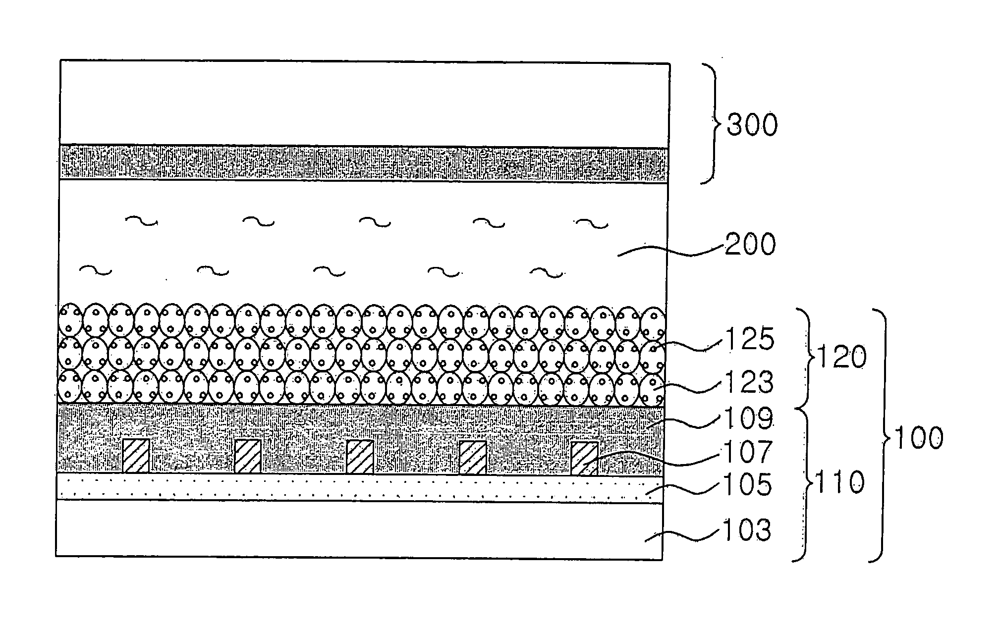
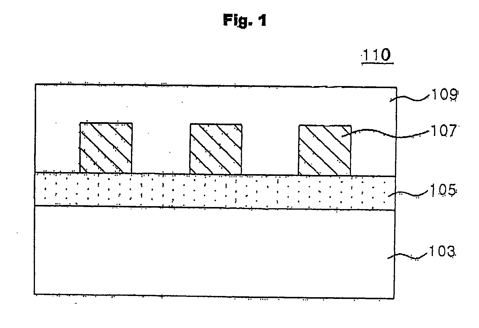
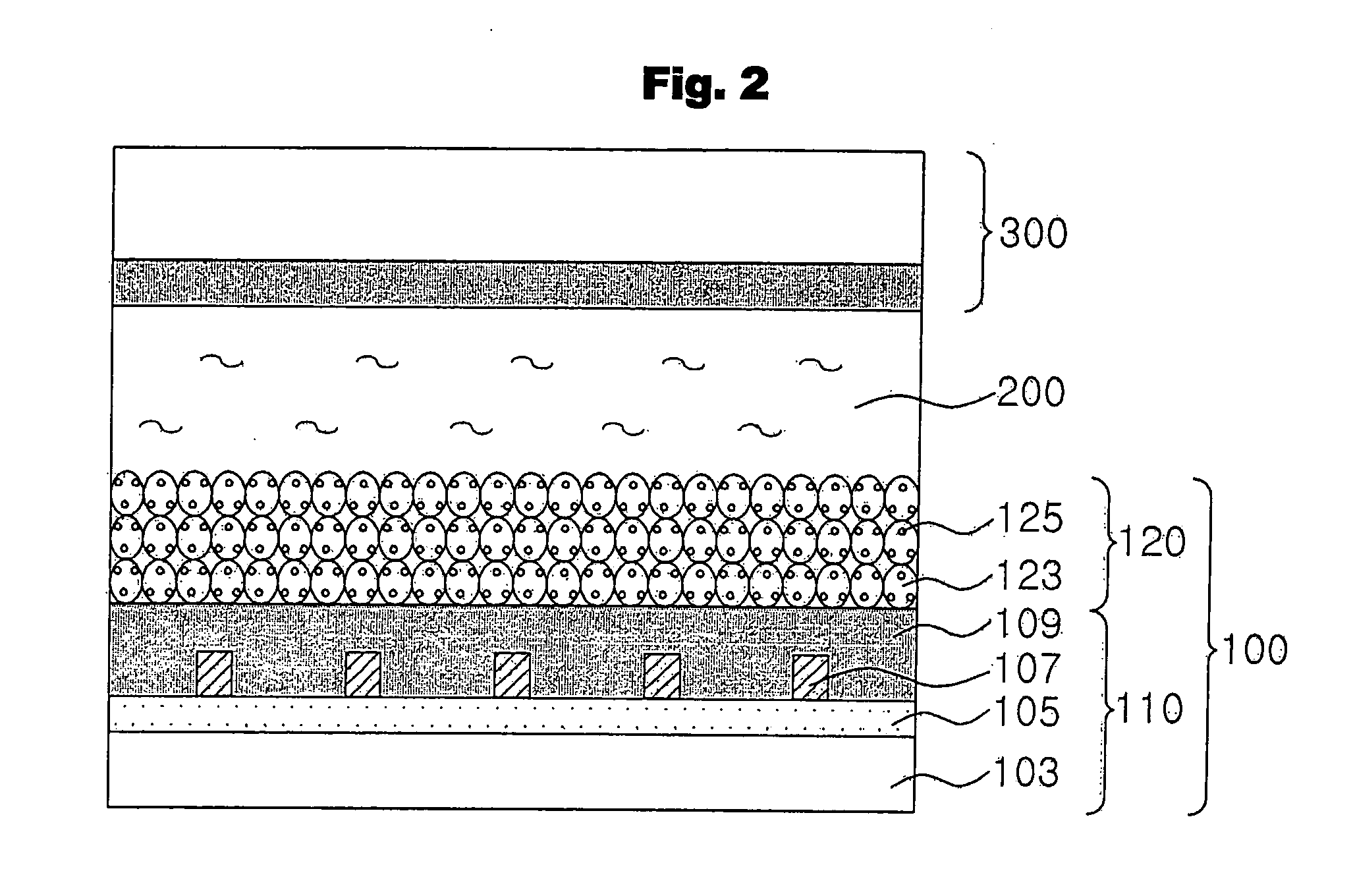
Disclosed herein is a transparent electrode for solar cells, comprising a transparent electrode, a photocatalytic layer formed on the transparent electrode and comprising a photocatalytic compound, a metal mesh layer formed on the photocatalytic layer, and an electrically conductive layer formed of an electrically conductive material coated on the metal mesh layer. Disclosed herein too is a manufacturing method thereof and a semiconductor electrode comprising the same. The disclosed transparent electrode includes a metal mesh layer formed in an existing transparent electrode for solar cells, and thus has low resistance without a reduction in transmittance. Accordingly, a solar cell that utilizes the disclosed transparent electrode has high-efficiency characteristics.

Description

BACKGROUND OF THE INVENTION [0001] This non-provisional application claims priority under 35 U.S.C. § 119(a) to Korean Patent Application No. 2005-103845 filed on Nov. 1, 2005, the entire contents of which are hereby incorporated by reference. [0002] 1. Field of the Invention [0003] The present invention relates to a transparent electrode for solar cells, a manufacturing method thereof and a semiconductor electrode comprising the same. The present invention more particularly relates to a transparent electrode for solar cells, wherein a metal mesh layer is formed in the existing transparent electrode for solar cells thereby displaying a high transmittance and electrical conductivity, as well as a manufacturing method thereof and a semiconductor electrode comprising the same. [0004] 2. Description of the Prior Art [0005] Solar cells, which comprise photoelectric conversion elements that convert solar light (visible electromagnetic radiation) into electricity, are sustainable and eco-f...

Claims


Application Information

Patent Timeline
IPC IPC(8): H01L31/00
CPCH01G9/2031H01G9/2059H01L51/445Y02E10/542Y02E10/549Y02P70/50H10K30/83H01L31/04H01L31/0224H01L31/18
Inventor CHO, SUNG HENSONG, KI YONGNOH, CHANG HOKIM, JIN YOUNG
Owner SAMSUNG ELECTRONICS CO LTD
Why Eureka
Eureka Blog
Learn More