
Fluid injection devices and analyzing and maintenance methods thereof

Inactive Publication Date: 2007-04-12
BENQ CORP
View PDF4 Cites 4 Cited by
  • Summary
  • Abstract
  • Description
  • Claims
  • Application Information

AI Technical Summary

Benefits of technology

[0013] Accordingly, the invention is directed to providing a fluid injection device integrating a surface acoustic wave (SAW) device. A SAW device using slanted finger inter-digital

Problems solved by technology

Therefore, the surface conditions of the injection device, including the ink residue, dust, environmental micro-particles and so forth, may have serious influence on the printing quality.
Moreover, the dried ink may make the nozzle clogged and then result in the failed nozzle causing bad printing quality; thus, to detect the conditions of the fluid injector device, to maintain the good conditions, and then to provide excellent printing quality is an important problem, which may be solved by adding an ink drying prevention mechanism or a nozzle cleaning mechanism to the fluid injection device.
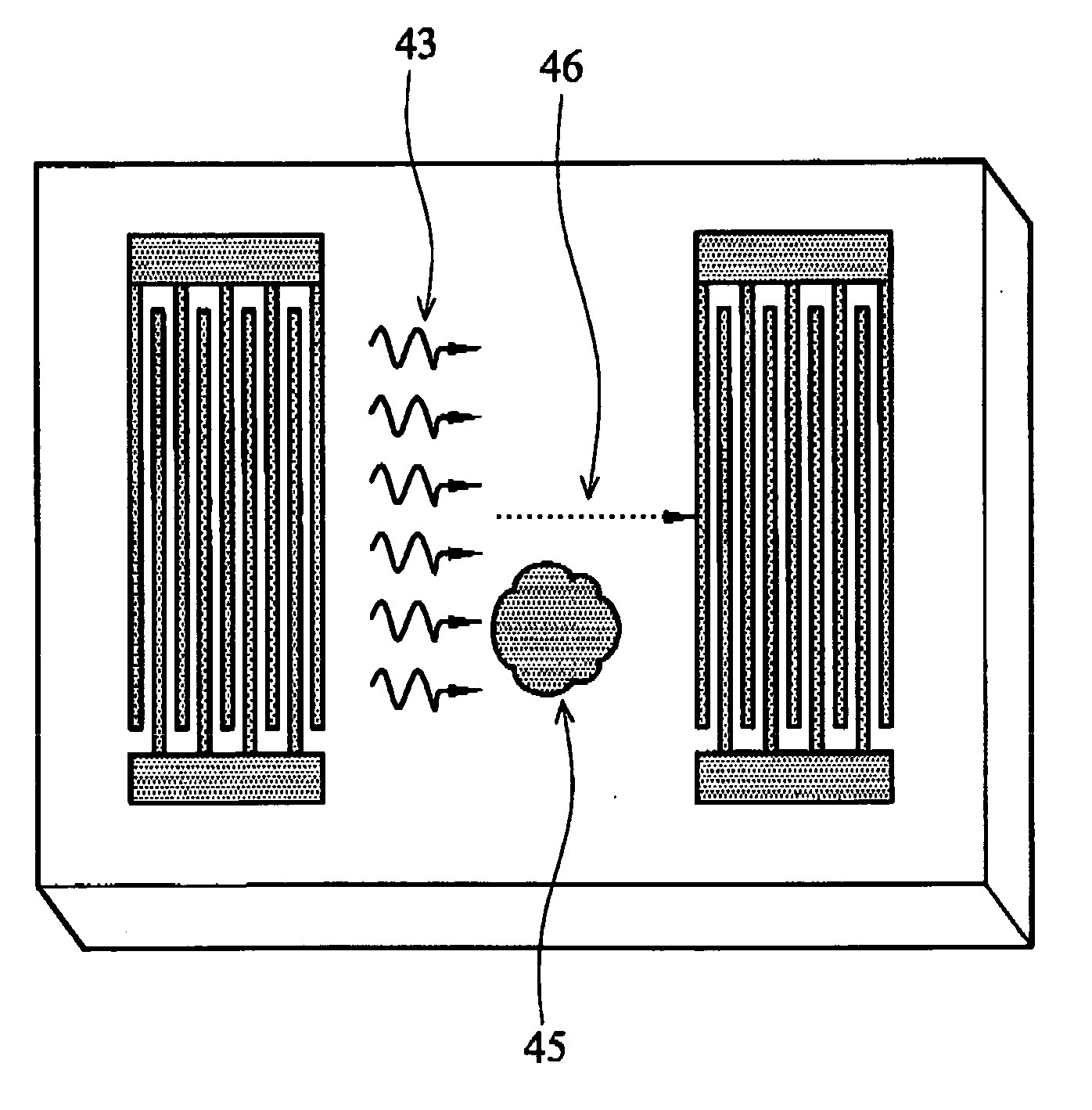
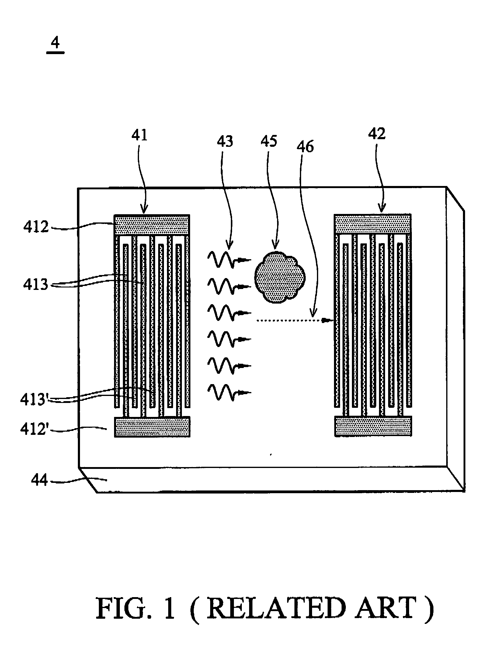
Conventional SAW sensors 4, however, cannot precisely detect the location of the contaminant 45.
Therefore, conventional SAW sensor 4 cannot differentiate contaminants at different locations.
Conventional methods of cleaning the nozzle surface require more space consumption and result in a more intricate fluid injection device.
Moreover, conventional wiping methods may further damage the nozzle surface.

Method used


Image

  • Fluid injection devices and analyzing and maintenance methods thereof
  • Fluid injection devices and analyzing and maintenance methods thereof
  • Fluid injection devices and analyzing and maintenance methods thereof

Examples


Embodiment Construction

[0051] The following description is of the best-contemplated mode of carrying out the invention. This description is made for the purpose of illustrating the general principles of the invention and should not be taken in a limiting sense. The scope of the invention is best determined by reference to the appended claims.

[0052] In a first aspect of the invention, a fluid injection device integrating a surface acoustic wave (SAW) device. A fluid injection element and a SAW device using slanted finger inter-digital transducers on the fluid injection element are provided. The fluid injection element comprises a fluid chamber on a substrate to accommodate fluid. A structural layer is disposed on the substrate. At least one fluid actuator is disposed on the structural layer opposing the fluid chamber. A nozzle is disposed adjacent to the fluid actuator and connecting the fluid chamber.

[0053] The following description is of the best-contemplated mode of carrying out the invention. This de...


PUM


Abstract

Fluid injection devices with surface acoustic wave (SAW) devices and methods of analyzing and cleaning the same. The fluid injection device comprises a fluid injection element and a surface acoustic wave device with slanted fingers inter-digital transducers on the fluid injection element. The fluid injection element comprises a fluid chamber in a substrate with a structural layer thereon. At least one fluid actuator is disposed on the structural layer opposing the fluid chamber. A nozzle adjacent to the at least one fluid actuator passes through the structural layer and connects the fluid chamber.

Description

BACKGROUND OF THE INVENTION [0001] 1. Field of the Invention [0002] The invention relates to fluid injection devices, and more particularly, to fluid injection devices with piezoelectric sensors and analysis and maintenance methods of the fluid injection devices. [0003] 2. Description of the Related Art [0004] Fluid injection devices have been employed in information technology industries for decades. As micro-system engineering technologies have developed, fluid injection devices have typically been applied in inkjet printers, fuel injection systems, cell sorting systems, drug delivery systems, print lithography systems and micro-jet propulsion systems. Among inkjet printers presently known and used, fluid injection devices can mainly be divided into two categories, continuous mode and drop-on-demand mode, depending on the fluid injection device. [0005] According to the driving mechanism, conventional fluid injection devices can father be divided into thermal bubble driven and piez...

Claims


Application Information

Patent Timeline
IPC IPC(8): F02M47/02B05B1/30F02M43/00B05B1/34
CPCB41J2/14072B41J2/14201B41J2/16517B41J2002/16567
Inventor LIN, CHIH MINGCHOU, CHUNG CHENG
Owner BENQ CORP
Learn More