
Toner for electrostatic latent image development and image forming method

a technology of latent image and toner, applied in the field of toner for electrostatic latent image development and image forming method, can solve the problems of reducing the charge quantity of the developing sleeve, affecting the quality of the image, so as to achieve uniform thickness and high quality. the effect of uniform thickness

Inactive Publication Date: 2007-01-11
KYOCERA DOCUMENT SOLUTIONS INC
View PDF1 Cites 1 Cited by
  • Summary
  • Abstract
  • Description
  • Claims
  • Application Information

AI Technical Summary

Benefits of technology

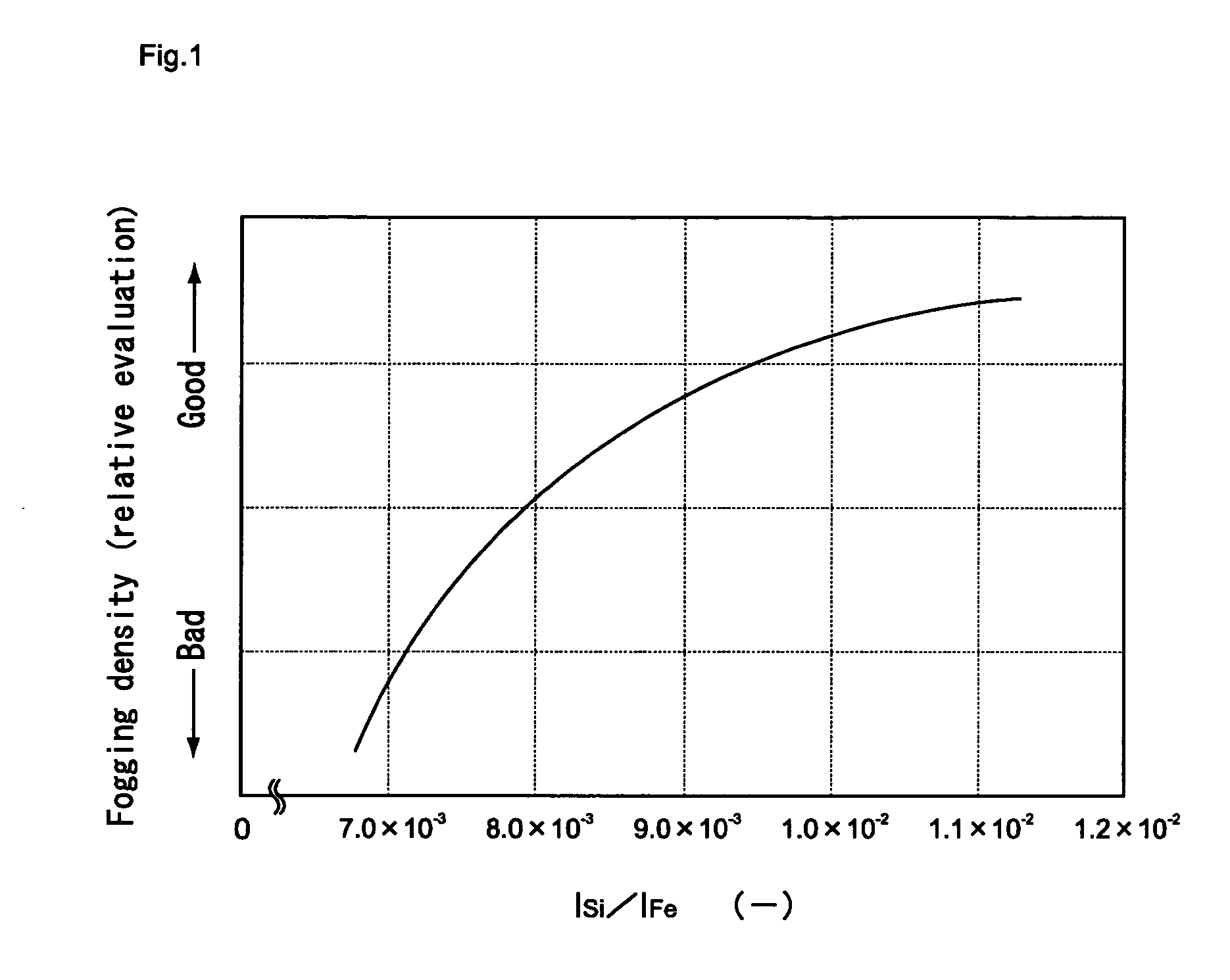
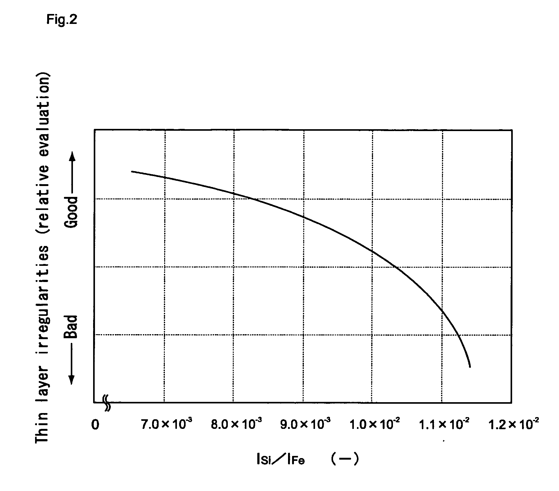
[0011] Here, the inventors of the present invention have found out that, by using a toner for electrostatic latent image development in which Si strength, Ti strength and Fe strength of the toner when these strengths are measured by using the fluorescent X-ray analyzing device satisfy a predetermined relationship, and which has a predetermined average degree of circularity, and by using a developing sleeve having a predetermined surface average gradient (Δa), it may be possible to effectively prevent a defective image which occurs due to the contamination of a surface of a photoconductor or a defective image which occurs attributed to the irregularity of a thickness of the thin toner layer on the sleeve. The inventors of the present invention have accomplished the present invention based on such findings.
[0035] Here, in the image forming method according to the present invention, even when the magnetic jumping method is used, it may be possible to maintain the thin toner layer on the developing sleeve uniformly, and even when the printing is repeated for a long time period, it may be possible to provide images having a high quality.

Problems solved by technology

However, since the two-component developing method uses a carrier and requires a mechanism which controls a mixing ratio of toner and carrier, the downsizing and the reduction of weight of the image forming apparatus are difficult.
However, as a first drawback of the magnetic jumping method, there exists the drawback that when the developing method is used under high moisture, a toner charging quantity on the developing sleeve is lowered and, as a result, a defect relating to an image such as thin density occurs.
Further, as a second drawback of the magnetic jumping method, there exists the drawback that when an amorphous silicon photoconductor having the substantially equal lifetime as an image forming apparatus is used, the moisture, the products formed by discharging such as ozone or NOx, a toner resin, a wax and the like are adhered to a photoconductor and hence, it is necessary to remove such adherents.

Method used


Image

  • Toner for electrostatic latent image development and image forming method
  • Toner for electrostatic latent image development and image forming method
  • Toner for electrostatic latent image development and image forming method

Examples


first embodiment

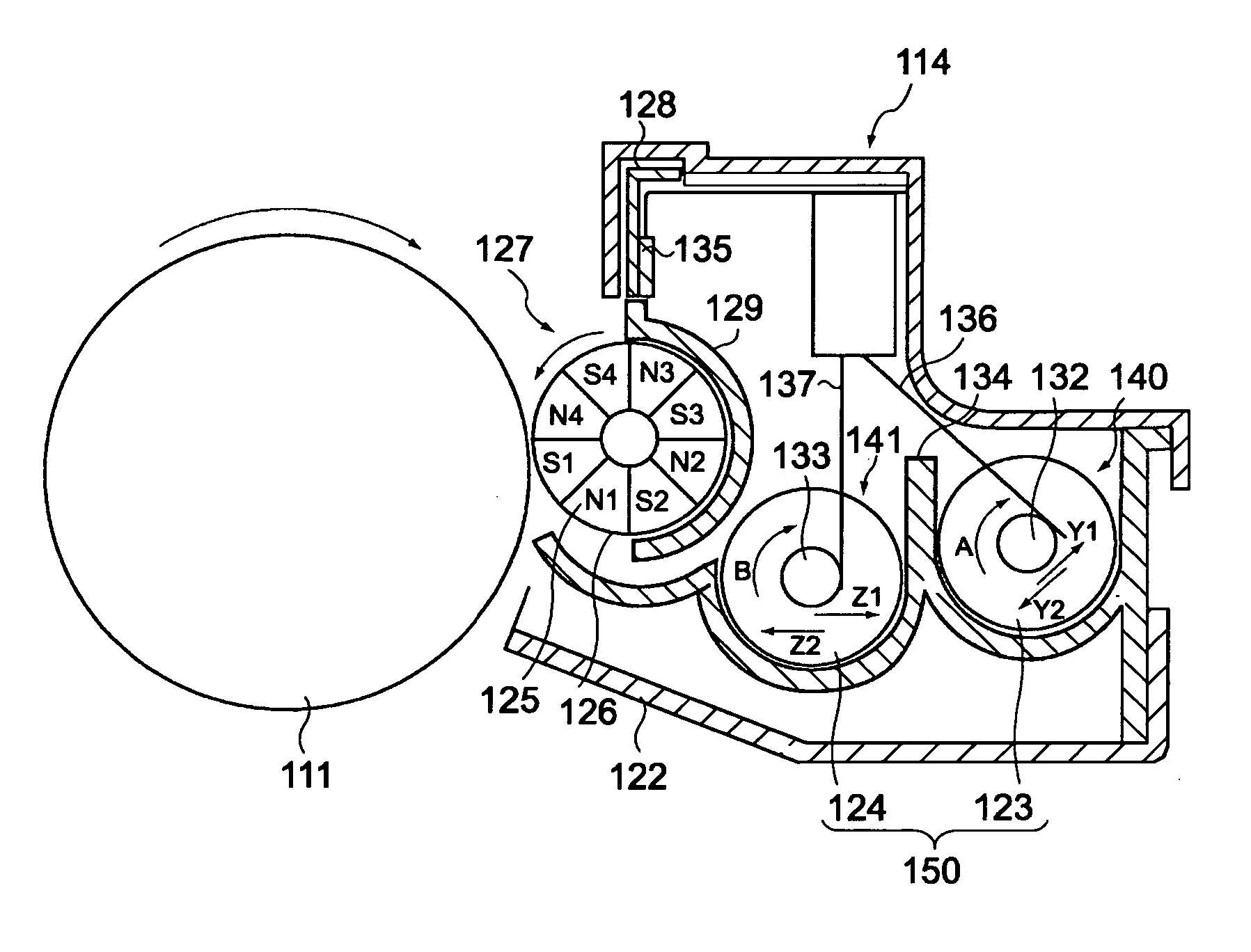
[0043] A first embodiment is directed to a toner for electrostatic latent image development which is used for an image forming apparatus including an electrophotographic photoconductor and a developing sleeve which is arranged close to the electrophotographic photoconductor, the toner being externally added with at least silica and titanium oxide to toner particles containing a magnetic powder, wherein assuming Si strength of the toner as ISi, Ti strength of the toner as ITi and Fe strength of the toner as IFe when these strengths are measured by using a fluorescent X-ray analyzing device, the following relationships (1) and (2) are satisfied, an average degree of circularity of the toner particles is set to a value which falls within a range from 0.940 to 0.960, and a surface average gradient of the developing sleeve (Δa) is set to a value which falls within a range from 0.1 to 0.25 rad.

9.0×10⁻³≦ISi / IFe≦1.0×10⁻²  (1)

6.0×10⁻³≦ITi / IFe≦8.0×10⁻³  (2)

1. Toner Particles

(1) Basic Co...

second embodiment

[0149] A second embodiment is directed to an image forming method in which a toner for electrostatic latent image development which is externally added with at least silica and titanium oxide to toner particles containing a magnetic powder is applied to a magnetic jumping method which uses an electrophotographic photoconductor and a developing sleeve arranged close to the electrophotographic photoconductor, wherein as the toner for electrostatic latent image development, the image forming method uses a toner for electrostatic latent image development which satisfies the following relationships (1) and (2) and sets Si strength of the toner as ISi, Ti strength of the toner as ITi and Fe strength of the toner as IFe when these strengths are measured by using a fluorescent X-ray analyzing device, and sets an average degree of circularity of the toner particles to a value which falls within a range from 0.940 to 0.960 and a surface average gradient (Δa) of the developing sleeve to a valu...

example 1

1. Preparation of Developing Sleeve

[0160] Bead blasting treatment is applied to a sleeve having a length of 300 mm which is made of SUS316 under predetermined blasting treatment conditions (a bead size, a bead collision speed) thus preparing a developing sleeve (S1) as shown in Table 1.

[0161] Here, a surface average gradient (Δa) of the developing sleeve is measured in accordance with JIS B0601. That is, the surface average gradient (Δa) is measured by the three-dimensional interference microscope WYKO NT1100 type (made by Veeco Instruments) under the following condition.

magnification of measuring lens: 10 times

measuring mode: VSL

measuring size: 2438×482 μm

sampling: 820.96 nm

[0162] The ten-point average roughness (Rz) and the average interval (Sm) of the developing sleeve are measured in accordance with JIS B0601 by using a surface texture measuring instrument (SURFCOM 1400D: made by Tokyo Seimitsu Co., Ltd.).

2. Formation of Toner for Electrostatic Latent Image Develop...


PUM


Abstract

The present invention provides a toner for a electrostatic latent image development and an image forming method which could print an image having the high quality for a long time period by forming a thin toner layer having a uniform thickness on a developing sleeve and, at the same time, by maintaining a surface of a photoconductor in the clean conditions irrespective of a change brought about by a lapse of time or an environmental change. In a toner for electrostatic latent image development which is used for an image forming apparatus comprising an electrophotographic photoconductor and a developing sleeve which is arranged close to the electrophotographic photoconductor, the toner is externally added with at least silica and titanium oxide to toner particles containing a magnetic powder, wherein assuming Si strength of the toner as ISi, Ti strength of the toner as ITi and Fe strength of the toner as IFe when these strengths are measured by using a fluorescent X-ray analyzing device, the following relationships (1) and (2) are satisfied. 9.0×10⁻³≦ISi / IFe≦1.0×10⁻²  (1) 6.0×10⁻³≦ITi / IFe≦8.0×10⁻³  (2)

Description

TECHNICAL FIELD [0001] The present invention relates to a toner for electrostatic latent image development which is used in an image forming apparatus such as a copying machine, a printer, a facsimile or a composite machine thereof which uses an electrophotographic method, and an image forming method which uses the toner for electrostatic latent image development. [0002] In general, a developing method adopted by an image forming apparatus such as a copying machine, a printer, a facsimile, a composite machine thereof or the like which uses an electrophotographic method is classified into a monocomponent developing method which uses a monocomponent developer and a two-component developing method which uses a two-component developer. [0003] However, since the two-component developing method uses a carrier and requires a mechanism which controls a mixing ratio of toner and carrier, the downsizing and the reduction of weight of the image forming apparatus are difficult. Accordingly, the...

Claims


Application Information

Patent Timeline
Patent Type & Authority Applications(United States)
IPC IPC(8): G03G21/00
CPCG03G9/0819G03G9/0821G03G2215/0619G03G9/083G03G9/0836G03G9/0827
Inventor KURAMASHI, KOJI
Owner KYOCERA DOCUMENT SOLUTIONS INC
Learn More