
Direct carbon fueled solid oxide fuel cell or high temperature battery

a carbon fueled solid oxide and high temperature battery technology, applied in the direction of cell components, primary cell maintenance/service, cell components, etc., can solve the problems of high cost of carbon electrode manufacture, and substantial barriers to achieving a practical carbon/air fuel cell. , to achieve the effect of reducing the effect of ash build-up and increasing the reaction ra

Inactive Publication Date: 2007-03-22
GAS TECH INST
View PDF4 Cites 30 Cited by
  • Summary
  • Abstract
  • Description
  • Claims
  • Application Information

AI Technical Summary

Benefits of technology

[0007] It is another object of this invention to provide a method and apparatus for direct conversion of solid carbon fuels in fuel cells which addresses the problems of ash build-up, anode reaction rate sluggishness, high carbon electrode manufacture cost, and complexity of distribution to the cells encountered in conventional fuel cells.
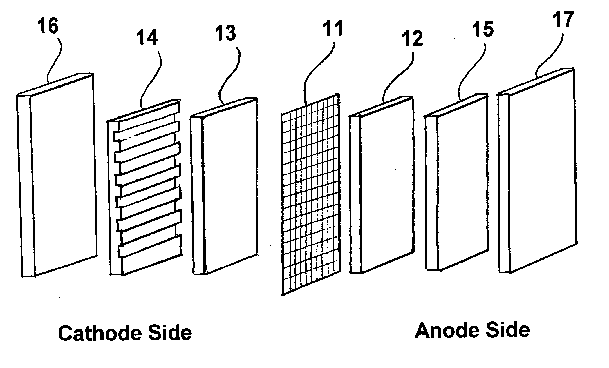
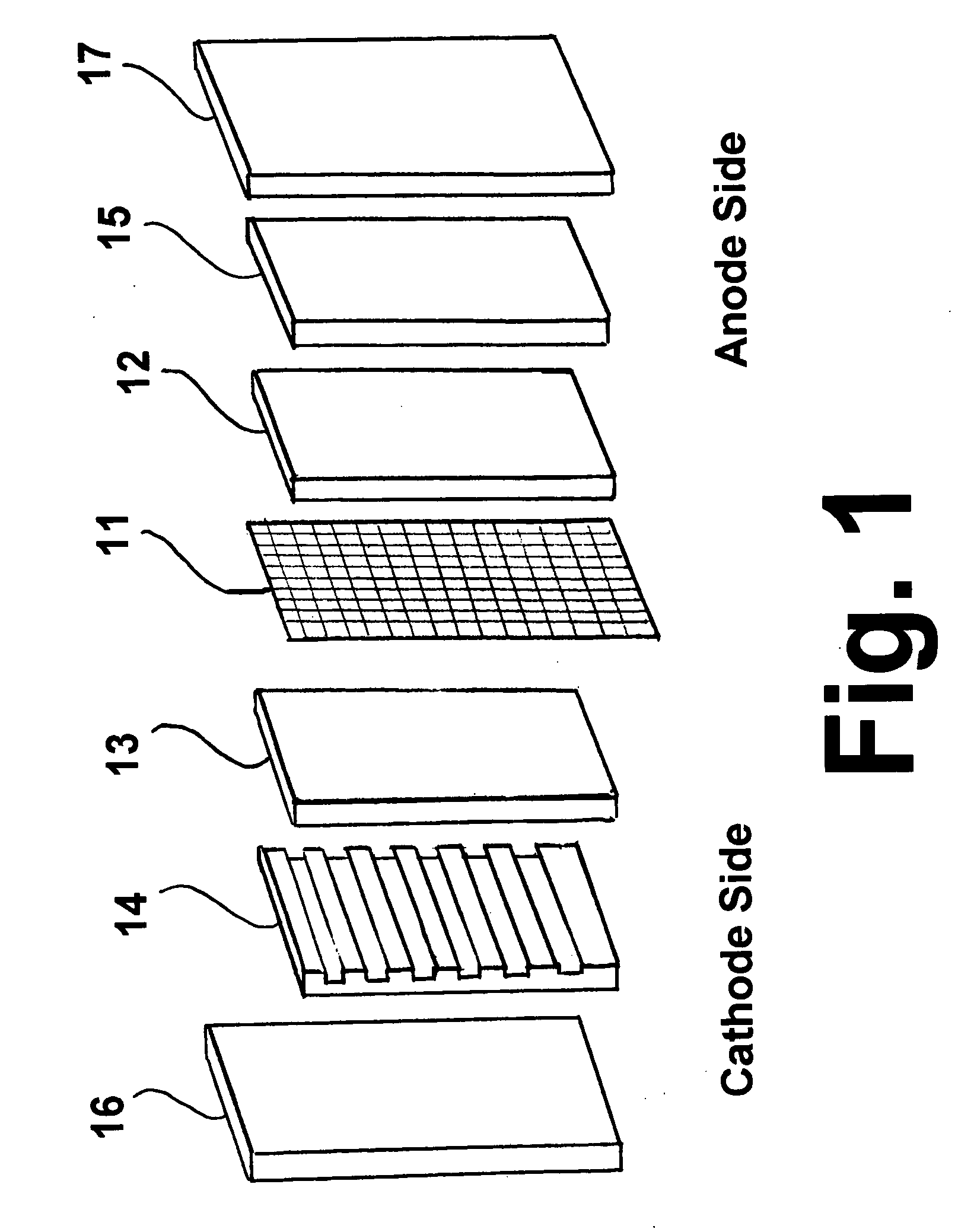
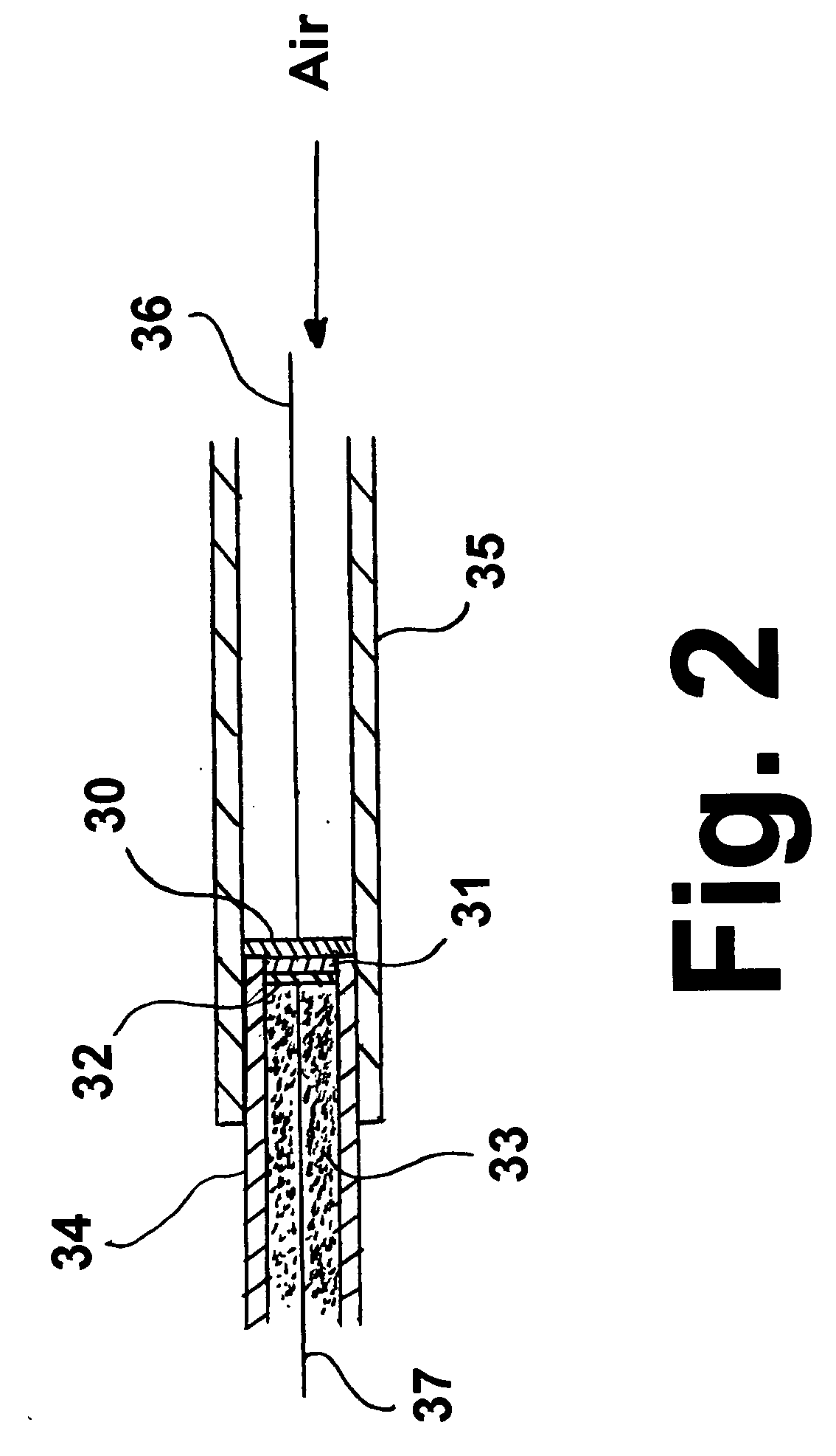
[0009] The benefits derived from the method and apparatus of this invention include reductions in the effect of ash build-up on the electrolyte, because the anode reactant carbon is mixed with a metal oxide, which is an O2− conductor. The ash components in the cell cannot block the transport path of the conductors because of the metal oxide bridge between the carbon and the electrolyte separator. Further benefits include increases in the anode reaction rates due to promotion of the solid carbon oxidation at elevated temperatures by the electrocatalyst of the transition metal oxide and elimination of the need to supply CO2 at the cathode side of the cell.

Problems solved by technology

However, substantial barriers for achieving a practical carbon / air fuel cell have been encountered.
These include blocking of the molten carbonate electrolyte by the build-up of ash, sluggishness of the anode reaction rate, and the high cost of carbon electrode manufacture and the complexity of distribution to the cells.
An additional drawback to this fuel cell is that the cathode reaction requires at least double the amount of CO2 than oxygen, which is not possible using normal air as the oxygen source.

Method used


Image

  • Direct carbon fueled solid oxide fuel cell or high temperature battery
  • Direct carbon fueled solid oxide fuel cell or high temperature battery
  • Direct carbon fueled solid oxide fuel cell or high temperature battery

Examples


Embodiment Construction

[0014] The invention disclosed and claimed herein is a direct carbon fuel electrochemical device in the form of a solid oxide fuel cell or high temperature battery. As used herein, the term “high temperature batteries” refers to batteries that are capable of operating at temperatures in the range of operating temperatures of solid oxide fuel cells. Also as used herein, the term “solid carbon” refers to all natural and synthetic substances comprising primarily carbon atoms and having the structure of graphite (graphitic carbon) or having a structure with at least two dimensionally ordered layers of carbon (non-graphitic carbon).

[0015] The invention disclosed and claimed herein is a direct carbon fueled solid oxide fuel cell or high temperature battery which is tolerant to impurities in the carbon fuel.

[0016] The invention disclosed and claimed herein is a direct carbon fueled solid oxide fuel cell or high temperature battery which is sulfur tolerant. This is of particular significa...


PUM


Abstract

A direct carbon fuel electrochemical device and method for generating electricity. The apparatus includes a solid oxide electrolyte having an anode side and a cathode side. Carbon and at least one metal oxide are provided to the anode side for reaction at the anode and air is provided to the cathode side. At least a portion of the carbon is oxidized and at least a portion of the metal oxide is reduced to a metal or lower oxide metal oxide on the anode side. The metal or lower oxide metal oxide is electrochemically reoxidized with oxygen in the air, thereby generating electricity.

Description

BACKGROUND OF THE INVENTION [0001] 1. Field of the Invention [0002] This invention relates to electrochemical devices for generating electricity, in particular, solid oxide fuel cells and high temperature batteries. This invention also relates to solid oxide fuel cells and high temperature batteries utilizing solid carbon directly as a fuel. This invention relates to coal fueled solid oxide fuel cells. This invention also relates to sulfur-tolerant solid oxide fuel cells. [0003] 2. Description of Related Art [0004] Fossil fuels including coal, oil and natural gas represent the majority of the world's energy supply, a fact which is likely to be true for the foreseeable future. Notwithstanding, extending the availability of these resources as well as reducing the costs and pollution associated with the use of these resources remain highly desirable objectives, objectives which can be addressed by improvements in the efficiencies of fuel utilization and fuel conversion. Methods and dev...

Claims


Application Information

Patent Timeline
IPC IPC(8): H01M8/06H01M8/18
CPCH01M4/8657H01M4/9016H01M4/92Y02E60/525H01M8/1246H01M2004/8684Y02E60/521H01M8/1233Y02E60/50Y02P70/50
Inventor FAN, QINBAILIU, RENXUAN
Owner GAS TECH INST
Learn More