
Apparatus and Method for Facilitating Data Packet Transportation

a data packet and apparatus technology, applied in data switching networks, frequency-division multiplexing, instruments, etc., can solve problems such as difficult traditional multiplexing schemes, inability to efficiently use communication channels under congested conditions, and limiting jitter to acceptable levels, so as to facilitate the minimization of jitter and transportation, simplify the multiplexing and demultiplexing of synchronous data, and reduce the time needed

Inactive Publication Date: 2007-03-22
TELLABS RESTON LLC
View PDF23 Cites 16 Cited by
  • Summary
  • Abstract
  • Description
  • Claims
  • Application Information

AI Technical Summary

Benefits of technology

[0007] An object of the present invention is to efficiently transport synchronous data with limited jitter over a communication channel while making the remaining available bandwidth of the channel available for the transport of asynchronous data. A further object of the present invention is to provide congestion management for ring-based communication systems. Advantages of the present invention are that jitter is limited, multiplexing and demultiplexing of synchronous data is simplified, and otherwise unused bandwidth is made available for the transport of asynchronous data. A further advantage of the present invention is that high-priority traffic being transported on ring-based communication channels may be assigned sufficient bandwidth for transmission on the ring even during periods of congestion, while other traffic is efficiently provided with ring bandwidth as it becomes available.
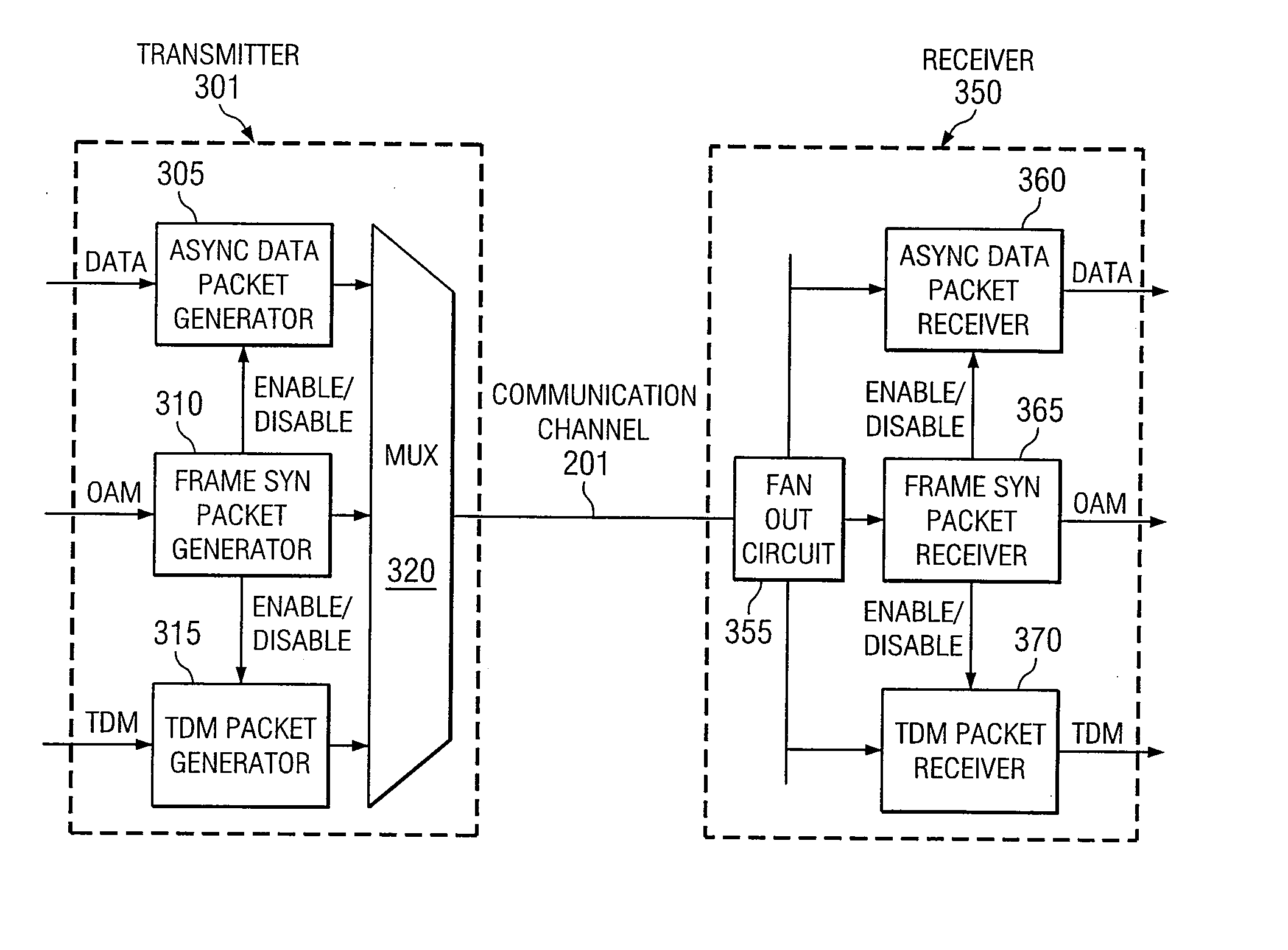
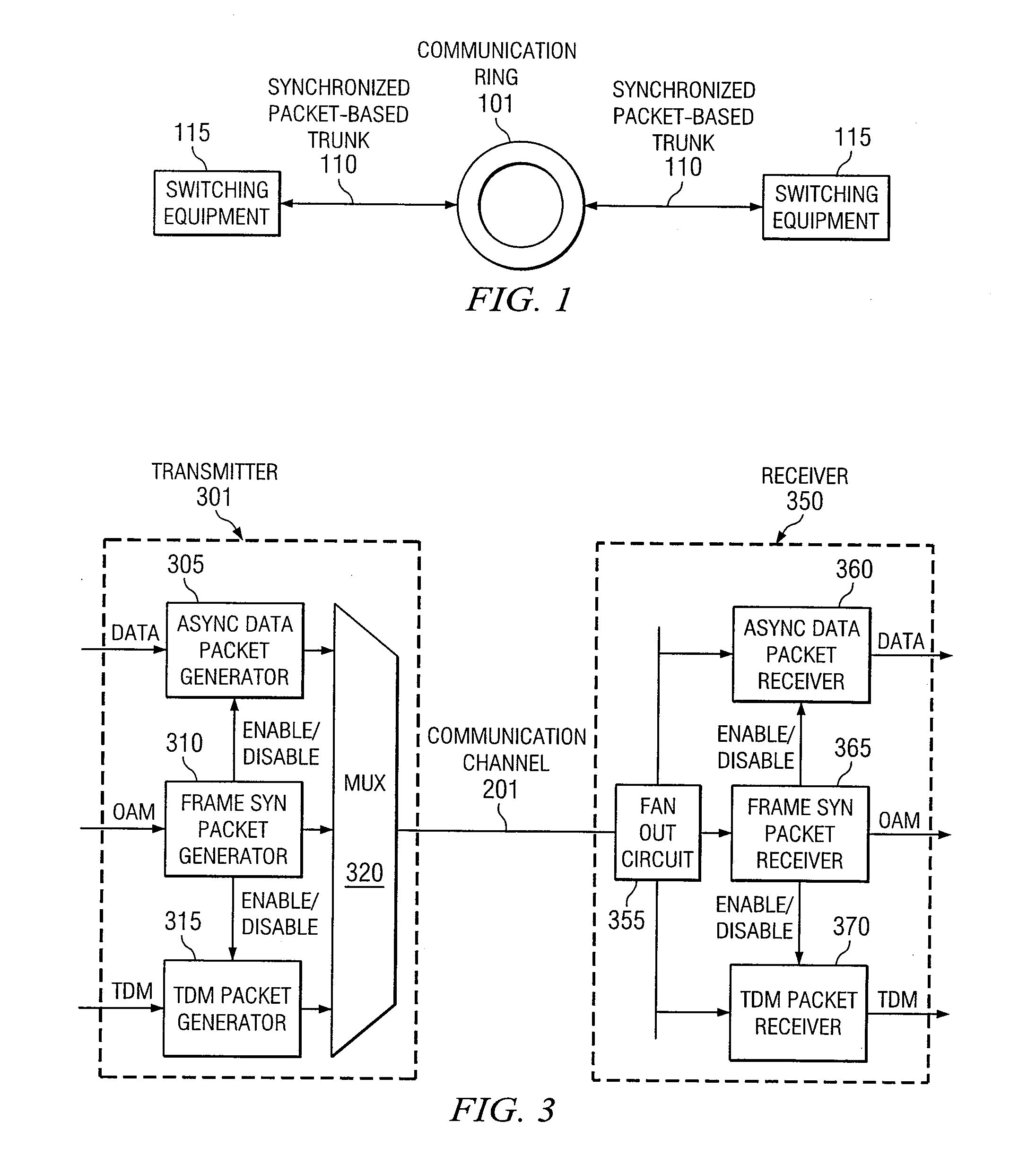
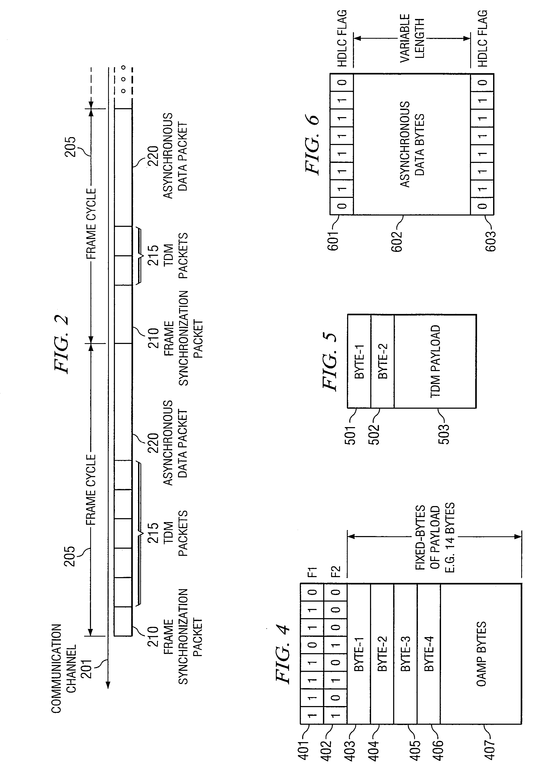
[0008] Some embodiments of the present invention inject a timing synchronization signal into a communication channel to facilitate the minimization of jitter and the transportation of asynchronous data, and to simplify the multiplexing and demultiplexing of synchronous data. The timing synchronization signal is injected into the data stream on the communication channel at fixed time intervals and is used to regulate the timing of all synchronous data, including Time Division Multiplex data (“TDM”), and asynchronous data transportation on the channel. In some embodiments, the timing synchronization signal is carried in a fixed-length frame synch packet with a unique frame code that is transported unscrambled in order to reduce the time needed to re-synchronize to the timing synchronization signal.
[0009] In some embodiments of the present invention, the synchronous data, including TDM data, is transported in a synchronous data packet with the payload length of the synchronous data packet being indicated by a length indication byte in the header of the packet. In some embodiments, synchronous data packets from a particular synchronous input channel will be injected into the communication channel at a particular, fixed, predetermined time in relation to the timing packet. This predetermined time is assigned to the synchronous input channel during service provisioning time and may be adjusted as additional synchronous input channels are provisioned.
[0010] In some embodiments of the present invention, the bandwidth on the communication channel that is not reserved for synchronous data and the timing synchronization signal is provisioned as a single sub-channel for asynchronous (including High Level Data Link Control (HDLC)) data packets. The incoming asynchronous data stream is packetized and inserted into the sub-channel at those time intervals that are not reserved for synchronous data or the timing synchronization signal.
[0011] Some embodiments of the present invention, related to communication rings, assign a baseline amount of bandwidth (the “subscription” bandwidth) and an Acceptable Over-Subscription Bandwidth to each communication node on a communication ring. The maximum amount of ring bandwidth that a node is permitted to use at any particular time, in addition to the node's baseline subscription bandwidth, is the node's Access Bandwidth. The actual ring bandwidth available to a node at any particular time, in addition to the node's baseline subscription bandwidth, is the node's actual Over-Subscription Bandwidth. For each node, if the amount of over-subscription bandwidth available on the ring is less than the Acceptable Over-Subscription Bandwidth and the node's over-subscription traffic that is ready to be sent to the ring requires more than the node's actual Over-Subscription Bandwidth, then an access congestion indication will be sent to the rest of the nodes on the ring.
[0012] Further, a Maximum Over-Subscription bandwidth is also assigned to each communication node. Each node will not send more over-subscription traffic than the Maximum Over-Subscription Bandwidth. The Maximum Over-Subscription Bandwidth of particular nodes is set at the service provisioning time, as is known in the art, based on factors including the traffic types and number of customers, thus providing access fairness for each node and minimizing the effect of location-dependent advantages.

Problems solved by technology

While packet switching systems are well known in the art, such systems may not be able to efficiently use communication channels under congested conditions or when combinations of synchronous and asynchronous data must be transported.
The efficient transmission of combinations of asynchronous data and synchronous data, while limiting jitter to acceptable levels, however, has proven to be difficult for traditional multiplexing schemes.
A number of such methods are known in the art, but may not be suitable for use on ring-based communication systems that cover large geographic areas due to time delays, or may otherwise introduce significant inefficiencies in the operation of the communication network.

Method used


Image

  • Apparatus and Method for Facilitating Data Packet Transportation
  • Apparatus and Method for Facilitating Data Packet Transportation
  • Apparatus and Method for Facilitating Data Packet Transportation

Examples


Embodiment Construction

Interpretation of Terms

[0040] Unless otherwise noted in this specification or in the claims, all of the terms used in the specification and the claims will have the meanings normally ascribed to these terms by workers in the art. Certain terms specifically comprise the meanings associated with them as follows:

[0041]“Computer system” refers to individual standalone computers, multiple computers coupled in any manner, and software simulations of computers regardless of the intended use of the computer system or the technology used to implement the computer system. The term “Computer system” includes, but is not limited to, packet-switching systems and other communication switching systems.

[0042]“Frame Cycle” refers to the time period on a communication channel beginning with the start of the transmission of a Frame Synchronization Packet and ending with the start of the transmission of the next subsequent Frame Synchronization Packet on that communication channel. In some embodime...


PUM


Abstract

Embodiments of the present invention described and shown in the specification and drawings facilitate data packet transportation. One aspect of the invention multiplexes time-sensitive TDM (Time Division Multiplexed) and other synchronous data, and asynchronous data traffic, onto a communication channel in a manner that minimizes jitter in the delivery of the TDM data traffic while efficiently transporting asynchronous data traffic. Another aspect of the invention provides dynamic bandwidth sharing on a communication ring. The dynamic bandwidth sharing aspect of the present invention facilitates the efficient utilization of bandwidth of communication rings, particularly in those rings that cover large geographic areas.

Description

CROSS REFERENCE TO RELATED APPLICATIONS [0001] This application is a continuation application of U.S. application Ser. No. 09 / 935,781 filed Aug. 24, 2001 and now U.S. Pat. No. 7,103,063 issuing on Sep. 5, 2006 which claims priority under to U.S. Provisional Application No. 60 / 227,521 filed Aug. 24, 2000, each of which is hereby incorporated herein by reference.TECHNICAL FIELD OF THE INVENTION [0002] The present invention generally relates to packet-based switching systems, and more particularly to apparatuses and methods for facilitating the transportation of data packets. BACKGROUND OF THE INVENTION [0003] While packet switching systems are well known in the art, such systems may not be able to efficiently use communication channels under congested conditions or when combinations of synchronous and asynchronous data must be transported. [0004] A variety of techniques are known in the art for multiplexing synchronous and asynchronous data onto communication channels. The efficient t...

Claims


Application Information

Patent Timeline
Patent Type & Authority Applications(United States)
IPC IPC(8): H04L12/42H04J3/06H04J3/08H04J3/16H04J3/24
CPCH04J3/1682H04L47/13H04L12/42H04J3/247
Inventor FANG, RONG C.
Owner TELLABS RESTON LLC
Learn More