
Diamondlike carbon hard multilayer film formed body and method for producing the same

a carbon hard, multi-layer technology, applied in the direction of superimposed coating process, transportation and packaging, vacuum evaporation coating, etc., can solve the problem of low adhesiveness to the substrate, large internal stress of dlc film with high hardness, and disadvantage of easy separation with low adhesiveness, etc. problems, to achieve the effect of improving adhesiveness, excellent adhesiveness and wear resistance, and improving adhesiveness

Inactive Publication Date: 2007-03-08
KOBE STEEL LTD
View PDF3 Cites 24 Cited by
  • Summary
  • Abstract
  • Description
  • Claims
  • Application Information

AI Technical Summary

Benefits of technology

The present invention provides a diamondlike carbon hard multilayer film formed body that exhibits excellent adhesiveness and wear resistance. This is achieved by forming an intermediate layer on a substrate and then sequentially depositing a first and second diamondlike carbon film on the intermediate layer. The surface hardness of the second diamondlike carbon film increases stepwise or continuously from the interface side between the first and second films towards the outermost layer. The substrate can be composed of cemented carbide or iron-based material, and the intermediate layer can be composed of a first metal layer and an amorphous layer containing at least one metal selected from the group consisting of W, Ta, Mo, and Nb, or a composite metal layer comprising a metal of Cr and / or Al and at least one metal selected from the group consisting of W, Ta, Mo, and Nb. The thickness of the intermediate layer is preferably between 10% and 50% of the total thickness of the diamondlike carbon hard multilayer film formed body. The method for producing the film formed body involves preparing a substrate, forming an intermediate layer on the substrate, and sequentially depositing a first and second diamondlike carbon film on the intermediate layer. The film formed body exhibits excellent adhesiveness and wear resistance even when a DLC multilayer film containing a high-hardness DLC film is formed on a substrate of a wide range of materials.

Problems solved by technology

However, a DLC film with high hardness has an extremely large internal stress, and its deformability is extremely small.
Therefore, it has a disadvantage of easily separating with low adhesiveness to the substrate.
However, in this method, since the mixing effect of C is used for forming the mixed layer as described above, the thickness of the mixed layer is limited to a narrow range from about 10 to 500 Å. Therefore, a hardness difference is caused between the substrate and the DLC film (in a case having no intermediate layer) or between the intermediate layer and the DLC film (in a case having the intermediate layer), which are arranged through such a thin mixed layer.
However, when the substrate is composed of a material with relatively low hardness such as an iron-based substrate, which is generally used for mechanical parts, easy separation of DLC film becomes problematic.
When the thickness of a multilayer film containing DLC film on the outermost surface side (a multilayer film including the intermediate layer and the DLC film, which may be hereinafter called DLC multilayer film) is as thick as not less than about 3 μm, this problem becomes noticeable because the whole stress of the DLC multilayer film is increased.
However, it is principally difficult for the sputtering including UBM sputtering to form a DLC film with extremely high hardness as in the AIP which uses carbon ion as a raw material.
Therefore, the DLC film formed using the sputtering is inferior in wear resistance to the DLC film formed using AIP.

Method used


Image

  • Diamondlike carbon hard multilayer film formed body and method for producing the same
  • Diamondlike carbon hard multilayer film formed body and method for producing the same
  • Diamondlike carbon hard multilayer film formed body and method for producing the same

Examples


embodiment 1

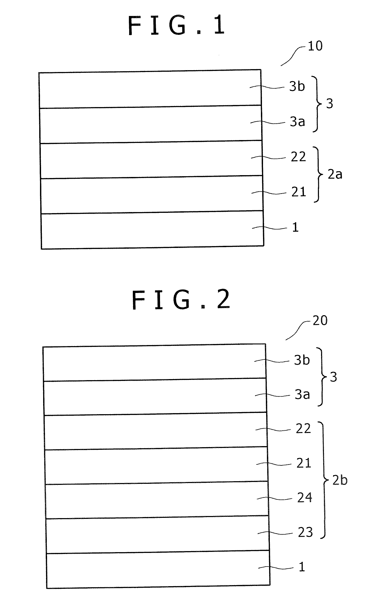
[0043] A first embodiment of the DLC formed body according to the present invention (referred to as first DLC formed body) is described in reference to FIG. 1. The first DLC formed body is useful, for example, for use of a substrate with relatively high hardness such as cemented carbide material, and the intermediate layer described in JP No. 2000-119843 is typically used as the intermediate layer.

[0044] A first DLC formed body 10, as shown in FIG. 1, comprises a substrate 1, a diamondlike carbon film mainly composed of diamondlike carbon (DLC film) 3, an intermediate layer 2 between the substrate 1 and the DLC film 3 (which may be called a first intermediate layer 2a for discrimination from a second intermediate layer described later).

[0045] The DLC film 3 is composed of, in order from the substrate 1 side, a first DLC film 3a and a second DLC film 3b, with the surface hardness of the first DLC film 3a being within the range from not less than 10 GPa to not more than 40 GPa based...

embodiment 2

[0061] A second embodiment of the DLC formed body according to the present invention (second DLC formed body) will be described in reference to FIG. 2. In FIG. 2, the same reference numbers as in FIG. 1 are assigned to parts overlapping with those of the first DLC formed body.

[0062] The second formed body is differed from the first formed body in the point that the intermediate layer is composed of four layers, and an iron-based material (preferably, a material with relatively low hardness such as bearing steel) is used as the substrate, as described below in detail. As the intermediate layer to be used in the second formed body, the intermediate layer described in JP No. 2003-171758 is typically given. Compared with the intermediate layer in the first DLC formed body, the third layer (metal layer) and the fourth layer (amorphous layer) in the second DLC formed body correspond to the first layer and the second layer in the first DLC formed body, respectively. Detailed descriptions ...

example

[0089] DLC formed bodies (Nos. 1 to 11) having various film structures shown in Table 1 were produced in the following manner, and evaluated for adhesiveness to the DLC film. Among them, Nos. 2 to 6 and 8 to 11 are inventive examples which satisfy the requirements of the present invention, and Nos. 1 and 7 are comparative examples which do not satisfy the requirements of the present invention. Each of Nos. 2 to 6 has a two-layer intermediate layer, and each of Nos. 8 to 11 has a four-layer intermediate layer.

(Substrate)

[0090] As shown in Table 1, cemented carbide (“UT120T” manufactured by Mitsubishi Materials Corporation) was used in Nos. 1 to 6, while SUJ2 of JIS standard was used in Nos. 7 to 12. Each substrate has a size of 12 cm square and 5 mm thickness, with a mirror-polished surface (Ra=about 0.02 μm).

[0091] These substrates were ultrasonically washed using an alkali tank in and a pure water tank in advance, and dried.

(Formation of Intermediate Layer and DLC Film)

(1) N...


PUM

PropertyMeasurementUnit
thicknessaaaaaaaaaa
thicknessaaaaaaaaaa
temperatureaaaaaaaaaa

Abstract

A diamondlike carbon hard multilayer formed film body comprises a substrate, a diamondlike carbon film mainly composed of diamondlike carbon, and an intermediate layer between the substrate and the diamondlike carbon film. The diamondlike carbon film is composed of, in order from the substrate side, a first diamondlike carbon film and a second diamondlike carbon film. The surface hardness of the first diamondlike carbon film is within the range from not less than 10 GPa to not more than 40 GPa based on nanoindentation test, and the surface hardness of the second diamondlike carbon film is within the range from more than 40 GPa to not more than 90 GPa based on nanoindentation test. According to such a structure, even if a DLC multilayer containing high-hardness DLC film on the outermost surface side is formed in a thickness of not less than about 3 μm on a substrate of a wide range extending from a material with high hardness such as cemented carbide to an iron-based material with low hardness, excellent adhesion to both the substrate and the DLC film can be ensured in addition to excellent wear resistance.

Description

BACKGROUND OF THE INVENTION [0001] 1. Field of the Invention [0002] The present invention relates to a hard multilayer film formed body which has a diamondlike carbon film on the outermost layer side, and a method for producing the same. The diamondlike carbon hard multilayer film formed body according to the present invention is suitably used for a surface protective film for a member which especially requires wear resistance in automobile parts, machine parts, precision tools, cutting tools, because it exhibits excellent adhesiveness to a substrate. [0003] 2. Description of the Related Art [0004] Diamondlike carbon (hereinafter referred to as “DLC”) is amorphous carbon having intermediate properties between diamond and graphite, and called hard carbon, hard amorphous carbon, amorphous carbon, delmorphous carbon, i-carbon, diamond-shape carbon or the like. The DLC is used, for example, as a protective film for a member which requires wear resistance because of high hardness as well...

Claims


Application Information

Patent Timeline
Patent Type & Authority Applications(United States)
IPC IPC(8): C23C14/00B32B9/00
CPCC23C14/024C23C14/0605C23C30/005C23C28/322Y10T428/30C23C28/325C23C28/343C23C28/347C23C28/321C23C28/323C23C14/00
Inventor AKARI, KOICHIROOOTA, AKITOSHI
Owner KOBE STEEL LTD
Learn More