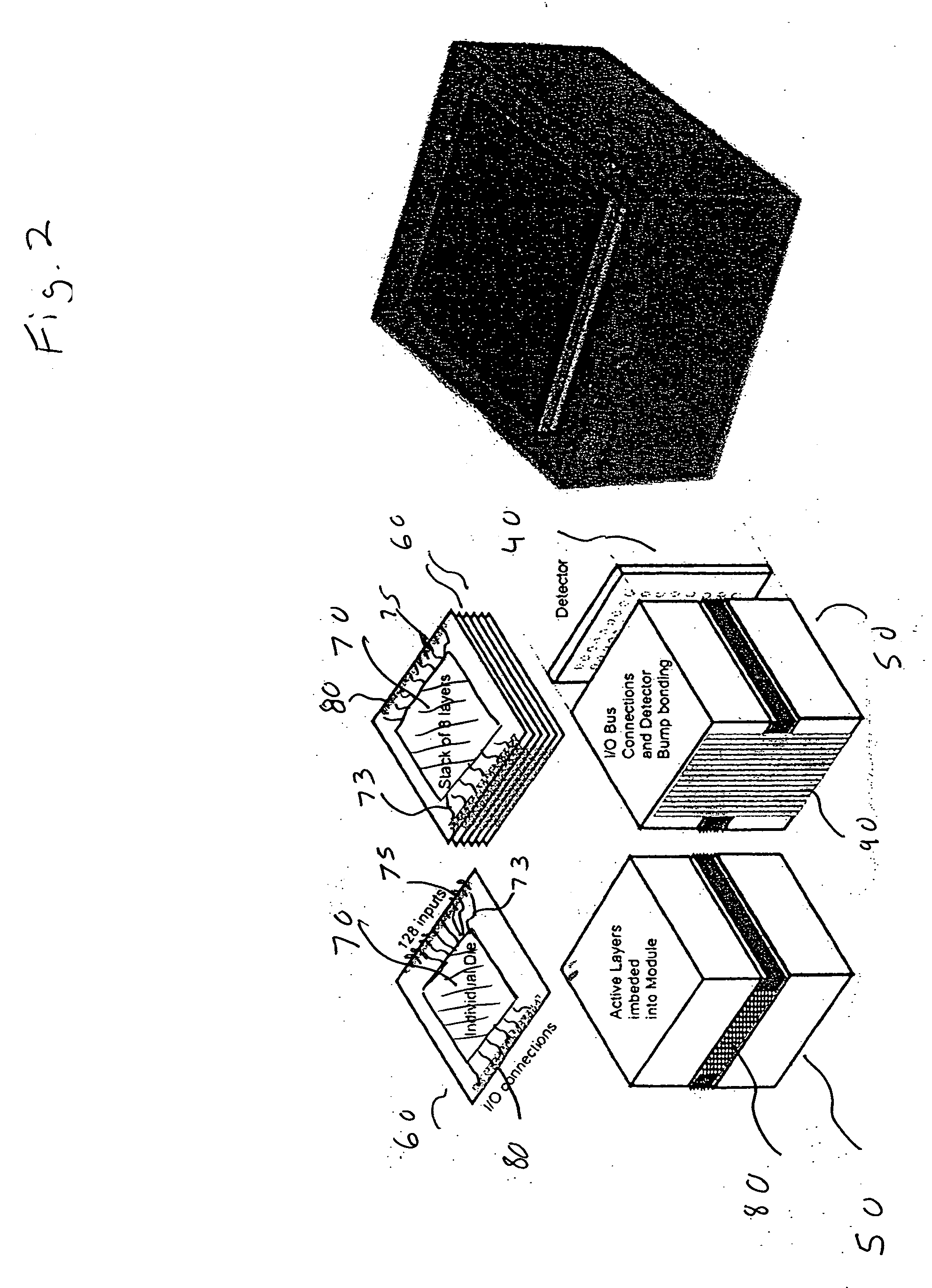
Three-dimensional imaging processing module incorporating stacked layers containing microelectronic circuits
a processing module and microelectronic circuit technology, applied in the field of ladar (laserradar) imaging technology, can solve the problems of undesirable sensor types, lack of circuit speed and capacity, and inability to achieve very high resolution and sensitivity in the centimeter range of existing ladar imaging systems
- Summary
- Abstract
- Description
- Claims
- Application Information
AI Technical Summary
Benefits of technology
Problems solved by technology
Method used
Image

Examples
Embodiment Construction
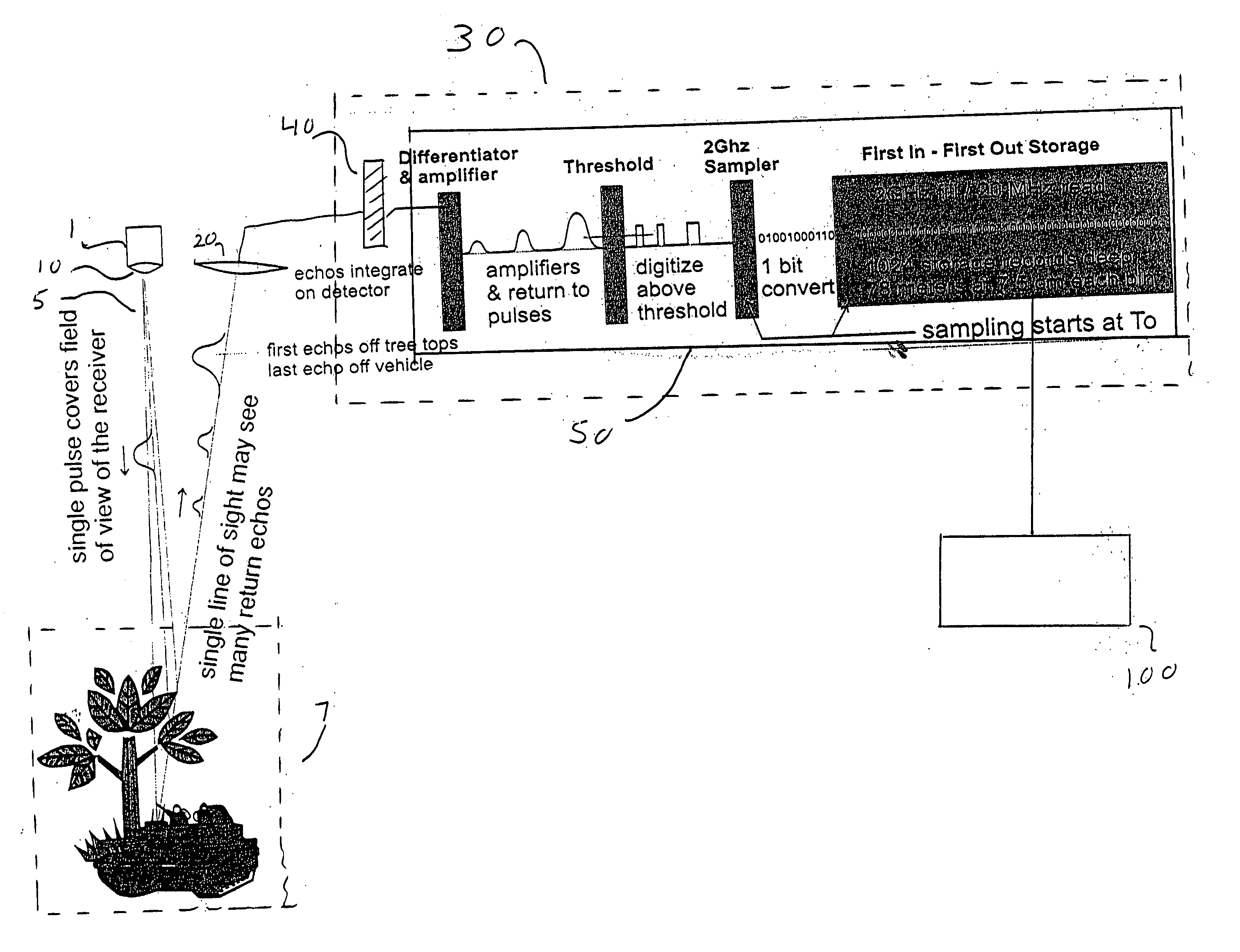
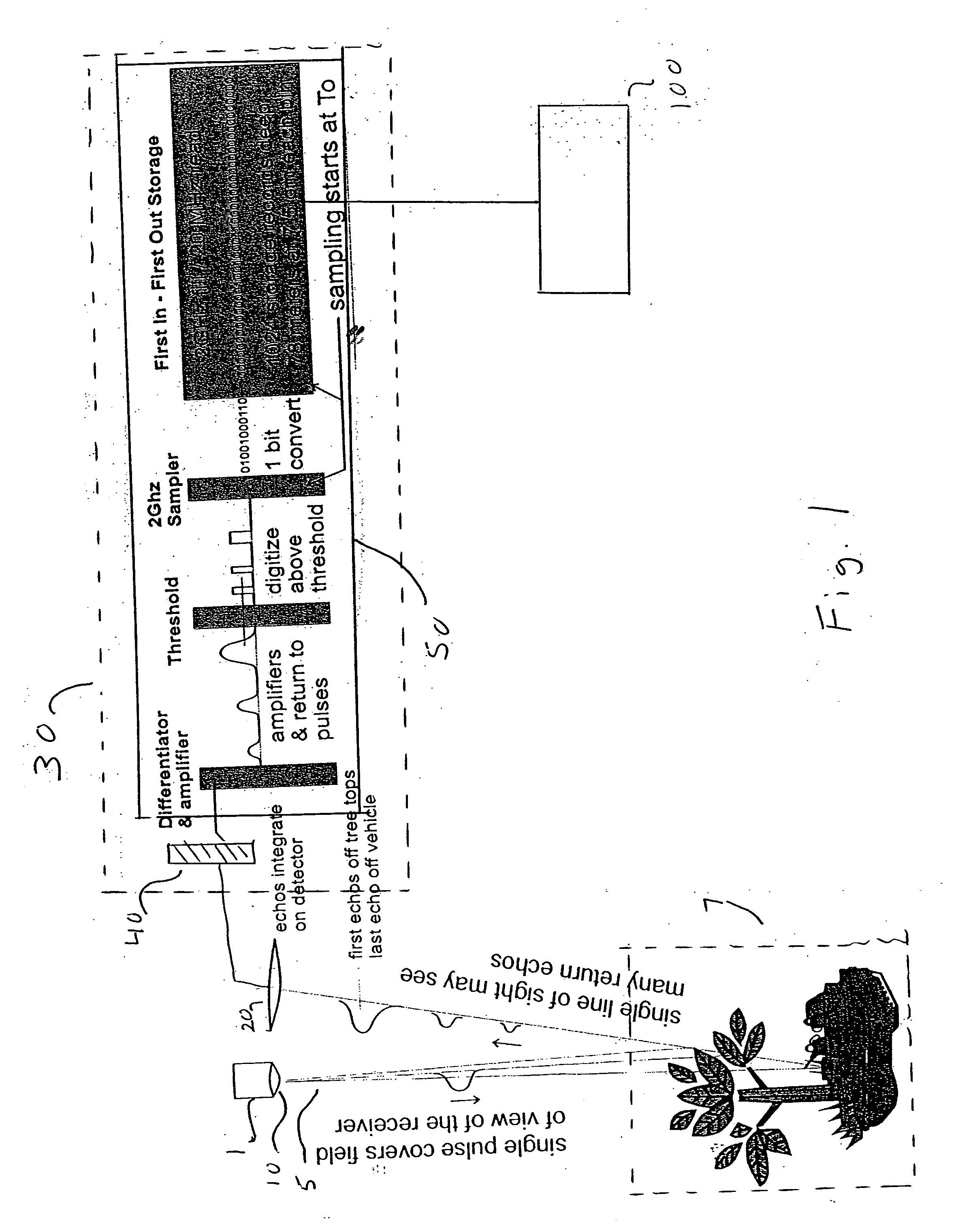
[0023] Turning now to the figures wherein like numerals designate like elements among the several views, FIG. 1 shows a block diagram of the present invention.
[0024] A photon source, such as a laser 1, generates a beam 5, which is directed toward a scene or target 7, through beam-shaping optics 10.
[0025] In a preferred embodiment, laser 1 is a 1064 nm, mechanically aligned, 300 micro-Joule, seed YAG laser capable of producing a pulse width of 500 picoseconds. In the preferred embodiment, a beam amplifier is provided (not shown), such as a master oscillator power amplifier wherein a seed beam is fed into the amplifier. In this preferred embodiment, the seed beam passes through a Faraday rotator and enters a four-pass, thermally controlled amplifier which includes two pumped YAG diodes.
[0026] In the preferred embodiment, beam-shaping optics 10 is a beam-shaping holographic lens suitable for projecting a rectangular beam area on a target. It has been determined that a rectangular be...
PUM
 Abstract
Description
Claims
Application Information
 - R&D
- Intellectual Property
- Life Sciences
- Materials
- Tech Scout
- Unparalleled Data Quality
- Higher Quality Content
- 60% Fewer Hallucinations
Browse by: Latest US Patents, China's latest patents, Technical Efficacy Thesaurus, Application Domain, Technology Topic, Popular Technical Reports.
© 2025 PatSnap. All rights reserved.Legal|Privacy policy|Modern Slavery Act Transparency Statement|Sitemap|About US| Contact US: help@patsnap.com