Eureka AIR delivers breakthrough ideas for toughest innovation challenges, trusted by R&D personnel around the world.

Uplink resource allocation to control intercell interference in a wireless communication system

a wireless communication system and resource allocation technology, applied in the direction of assessing restriction, power management, receiving monitoring, etc., can solve the problems of increasing interference level at the base station, degree of co-ordination, and interference degree, so as to avoid major increases in the complexity of ue receivers

Active Publication Date: 2007-02-22
SONY CORP
View PDF14 Cites 263 Cited by
  • Summary
  • Abstract
  • Description
  • Claims
  • Application Information

AI Technical Summary

Benefits of technology

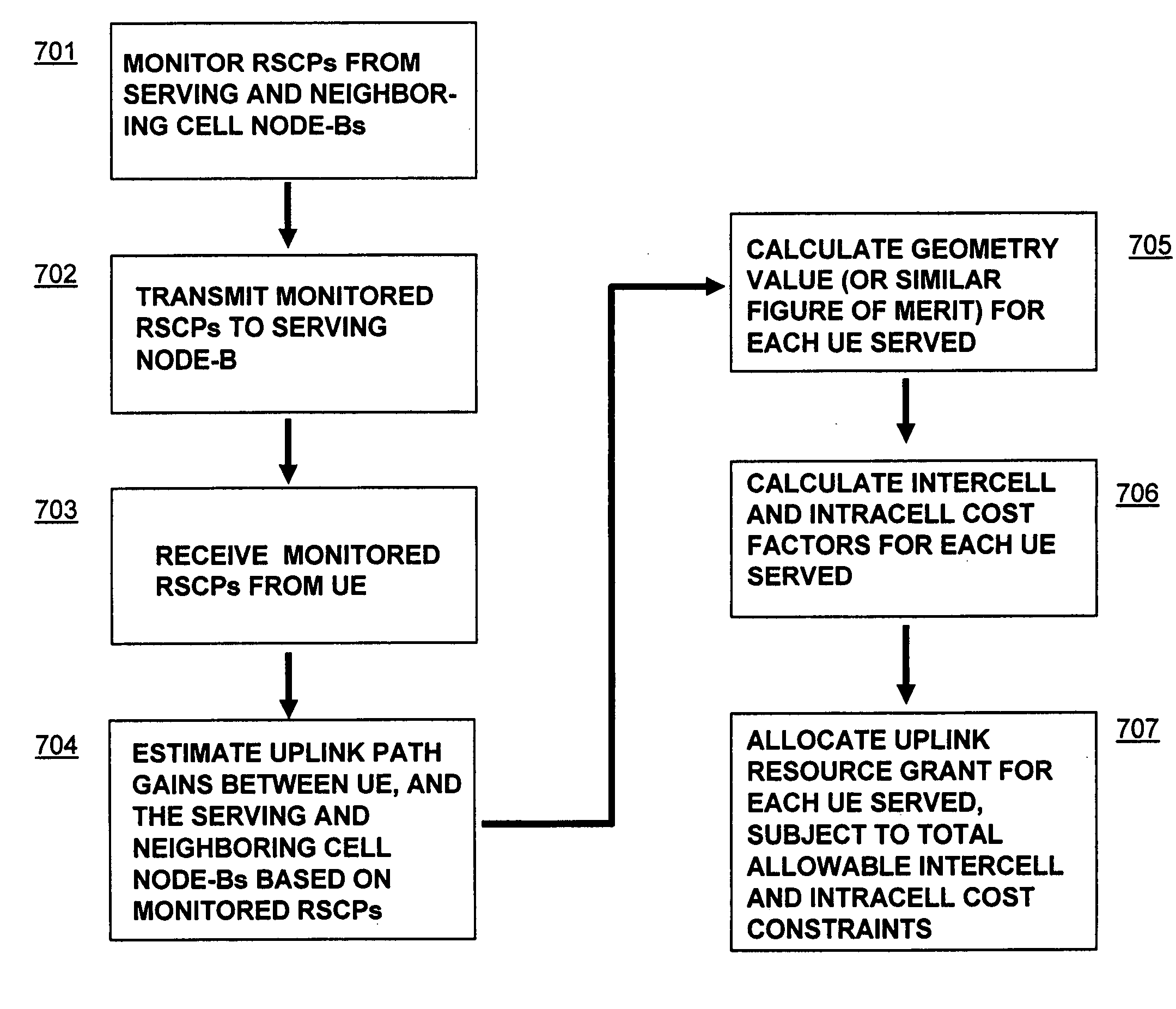
[0023] Embodiments of the present invention exploit the reciprocity of radio channels in TDD and FDD wireless communication systems to enable distributed schedulers in an enhanced uplink system to preemptively control intercell interference levels. Each cell's base station transmits a downlink reference (or so-called “beacon” signal) The transmission power of the beacon signal (at the transmitter) is known to the UE, because it is encoded on the beacon signal (and / or may be a default value). A UE monitors the received signal strength (received signal code power, “RSCP) of the downlink beacon signals from one or more base stations (received at the UE). The transmitted and received beacon signal power levels for the respective base stations (Node-Bs) are used by the UE to control the amount of inter-cell interference that the UE generates by its uplink transmissions. In further embodiments, the transmitted and received beacon signal power levels, or values derived therefrom, are transmitted by the UE to its serving Node-B (base station), where a transmission parameter scheduling mechanism is used to grant an uplink transmission parameter grant to the UE, thereby controlling the intercell interference generated by the UE's uplink transmissions. There is no need for the UE to receive data content from controlling signals from other (non-serving) cells, and as such embodiments of the present invention advantageously suit the characteristics of the current 3GPP TDD architecture and avoid major increases in UE receiver complexity.

Problems solved by technology

However, because uplink signals from a UE may significantly interfere with the operation of other cells, some degree of co-ordination is required between schedulers of different cells.
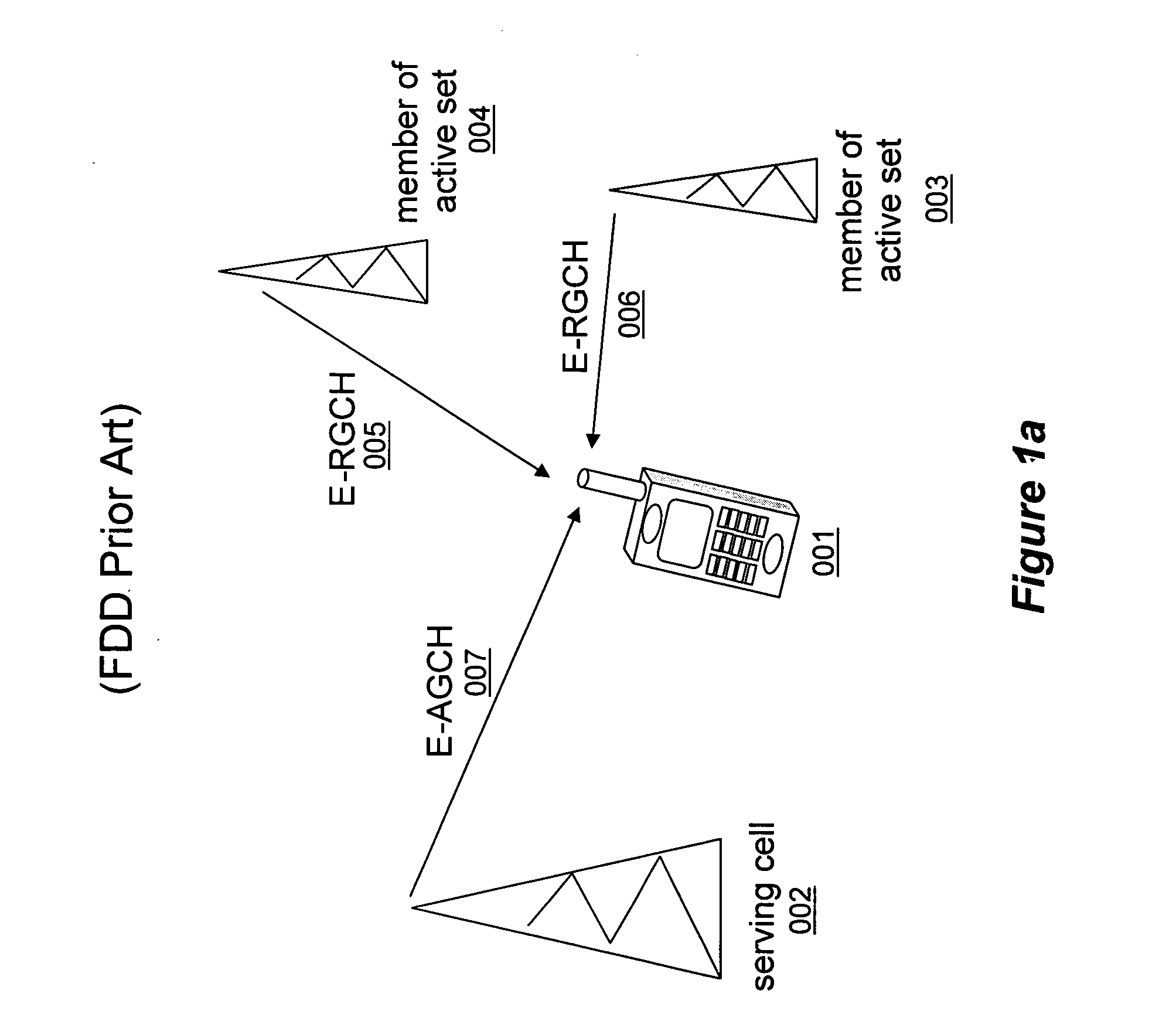
Due to the fact that in FDD WCDMA, uplink signals from each user interfere with those of other users, the transmission from UE 101 causes some degree of interference in cells 003 and 004.
As the allowable RoT set-point is increased, so the interference level at the base station increases and the harder it becomes for a UEs signal to be detected.
If a user is located close to a cell boundary, his uplink transmissions may contribute significantly to the received interference levels observed in a neighbor cell and may cause an allowable interference target in that cell to be exceeded.
This can reduce the coverage and degrade the radio communication in that neighbor cell.
This is an undesirable scenario, since decisions made by one scheduler in one cell may have a detrimental (and sometimes catastrophic) impact on the coverage or throughput in another cell.
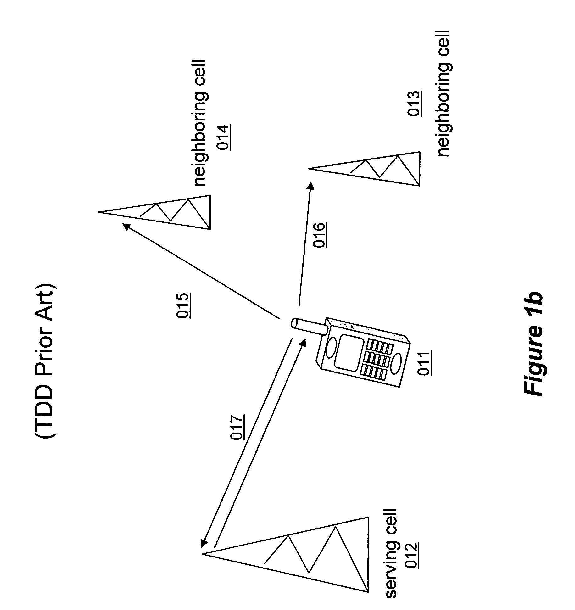
Uplink soft handover between cell sites is typically not supported for TDD.
Thus, the FDD solution to control intercell interference levels throughout the system using E-AGCH from serving cells and E-RGCH from neighboring cells is not appropriate for TDD enhanced uplink.
However, this would significantly increase the UE receiver complexity and for this reason, this is not an attractive solution.

Method used


Image

  • Uplink resource allocation to control intercell interference in a wireless communication system
  • Uplink resource allocation to control intercell interference in a wireless communication system
  • Uplink resource allocation to control intercell interference in a wireless communication system

Examples


Embodiment Construction

[0038] Unless defined otherwise, all technical and scientific terms used herein have the same meaning as is commonly understood by one of ordinary skill in the art to which this invention belongs. All patents, applications, published applications and other publications referred to herein are incorporated by reference in their entirety. If a definition set forth in this section is contrary to or otherwise inconsistent with a definition set forth in applications, published applications and other publications that are herein incorporated by reference, the definition set forth in this section prevails over the definition that is incorporated herein by reference.

[0039] As used herein, “a” or “an” means “at least one” or “one or more.”

[0040] In reference to FIGS. 2a and 2b, a UE 201 is in communication with its serving Node-B (base station) 202. The uplink signal also arrives at neighboring cell Node-Bs 203 and 204. There exists a signal path gain between each UE (denoted “i”) and each N...


PUM


Abstract

Embodiments of the present invention exploit the reciprocity of radio channels in TDD, and longer-term correlation between average uplink and downlink path losses in FDD wireless communication systems to enable distributed schedulers in an enhanced uplink system to allocate uplink transmission resources while preemptively managing intercell interference levels. Each cell's base station transmits a downlink reference signal at a known transmission power level. A mobile station monitors the received signal strength of the downlink reference signals from multiple base stations. The transmitted and received signal strength levels can be used by the mobile station to estimate the amount of intercell interference that the mobile station's uplink transmissions cause, and the mobile station's uplink transmission parameters are adjusted accordingly. In further embodiments, the received reference signal power levels, or values derived therefrom, are transmitted by the mobile station to its serving base station, where a scheduling algorithm uses the information to adjust one or more transmission parameters relating to a grant of uplink transmission resources to the UE, thereby controlling the intercell interference generated by the mobile station's uplink transmissions.

Description

TECHNICAL FIELD [0001] This invention relates to an interference control apparatus and method for uplink access in a wireless communication system. The invention is applicable to, but not limited to, a communication resource access, particularly for an enhanced uplink of packet-based data employed in a Universal Terrestrial Radio Access (UTRA) Wideband-CDMA system, as used in the Universal Mobile Telecommunication Standard (UMTS). BACKGROUND OF THE INVENTION [0002] Wireless communication systems, for example cellular telephony or private mobile radio communication systems, typically provide for radio telecommunication links to be arranged between a plurality of base transceiver stations (BTSs) and a plurality of subscriber units, often termed mobile stations (MSs). [0003] Wireless communication systems are distinguished over fixed communication systems, such as the public switched telephone network (PSTN), principally in that mobile stations move among BTS coverage areas, and in doi...

Claims


Application Information

Patent Timeline
Patent Type & Authority Applications(United States)
IPC IPC(8): H04Q7/20H04W52/34H04W72/14
CPCH04W24/10H04W48/16H04W52/34H04W72/082H04W72/1231H04W72/14H04L5/0073H04L5/006H04L5/14H04W52/283H04B17/24H04W16/14H04W72/542H04W72/541H04W72/23H04W72/21H04L5/22
Inventor ANDERSON, NICHOLAS WILLIAM
Owner SONY CORP
Why Eureka
Eureka Blog
Learn More