Variable slit apparatus, illumination apparatus, exposure apparatus, exposure method, and device fabrication method

a technology of illumination apparatus and slits, which is applied in the direction of lighting and heating apparatus, printing equipment, instruments, etc., can solve the problems of increasing the complexity of controlling the actuator, increasing the defect rate, and reducing the yield

Active Publication Date: 2007-01-18
NIKON CORP
View PDF16 Cites 45 Cited by
  • Summary
  • Abstract
  • Description
  • Claims
  • Application Information

AI Technical Summary

Benefits of technology

[0011] The first aspect of the present invention is a variable slit apparatus for forming a slit-shaped illumination light, comprising: a first light-shielding mechanism configured to comprise a plurality of blades for defining one long side of the illumination light; a second light-mechanism configured to define another long side of the illumination light; and a drive mechanism configured to drive at least one of the first light-shielding mechanism and the second light-shielding mechanism and changes the shape of the illumination light in the longitudinal direction. According to this aspect of the invention, the second light-shielding mechanism has a substantially linear light-shielding mechanism, and therefore can easily and rapidly correct the low order unevenness component of the illumination light. Furthermore, the first light-shielding mechanism can correct the high order unevenness component of the illumination light.
[0030] According to the fourth aspect of the present invention, defects in the line width of the pattern caused by illuminance unevenness are suppressed, and it is therefore possible to efficiently fabricate devices that comprise fine patterns. Furthermore, it is possible to efficiently achieve increased memory capacity of semiconductor memory, as well as increased speed and higher levels of integration of a CPU processor.

Problems solved by technology

On the other hand, the increased levels of integration and fineness of the patterns has given rise to an increased defect rate and decreased yield when exposure conditions change even slightly.
Nevertheless, there is a problem in that the increased number of blades commensurately increases the number of actuators, which increases the complexity of controlling the actuators and also decreases the throughput of the exposure apparatus because of the increased time needed to change the shape of the illumination light.
In addition, there is a problem in that the heat generated by the increased number of actuators adversely affects the exposure accuracy of the exposure apparatus.

Method used


Image

  • Variable slit apparatus, illumination apparatus, exposure apparatus, exposure method, and device fabrication method
  • Variable slit apparatus, illumination apparatus, exposure apparatus, exposure method, and device fabrication method
  • Variable slit apparatus, illumination apparatus, exposure apparatus, exposure method, and device fabrication method

Examples


Embodiment Construction

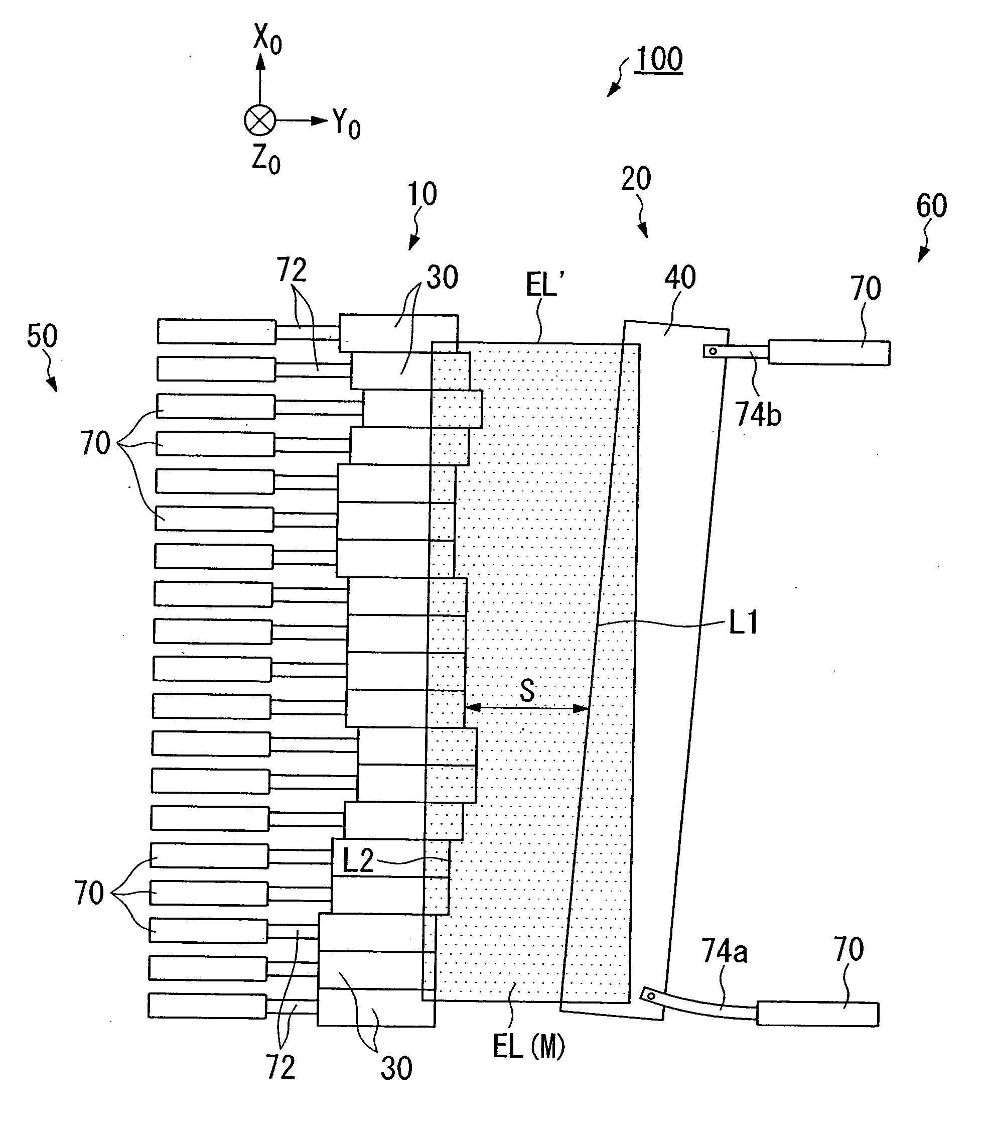
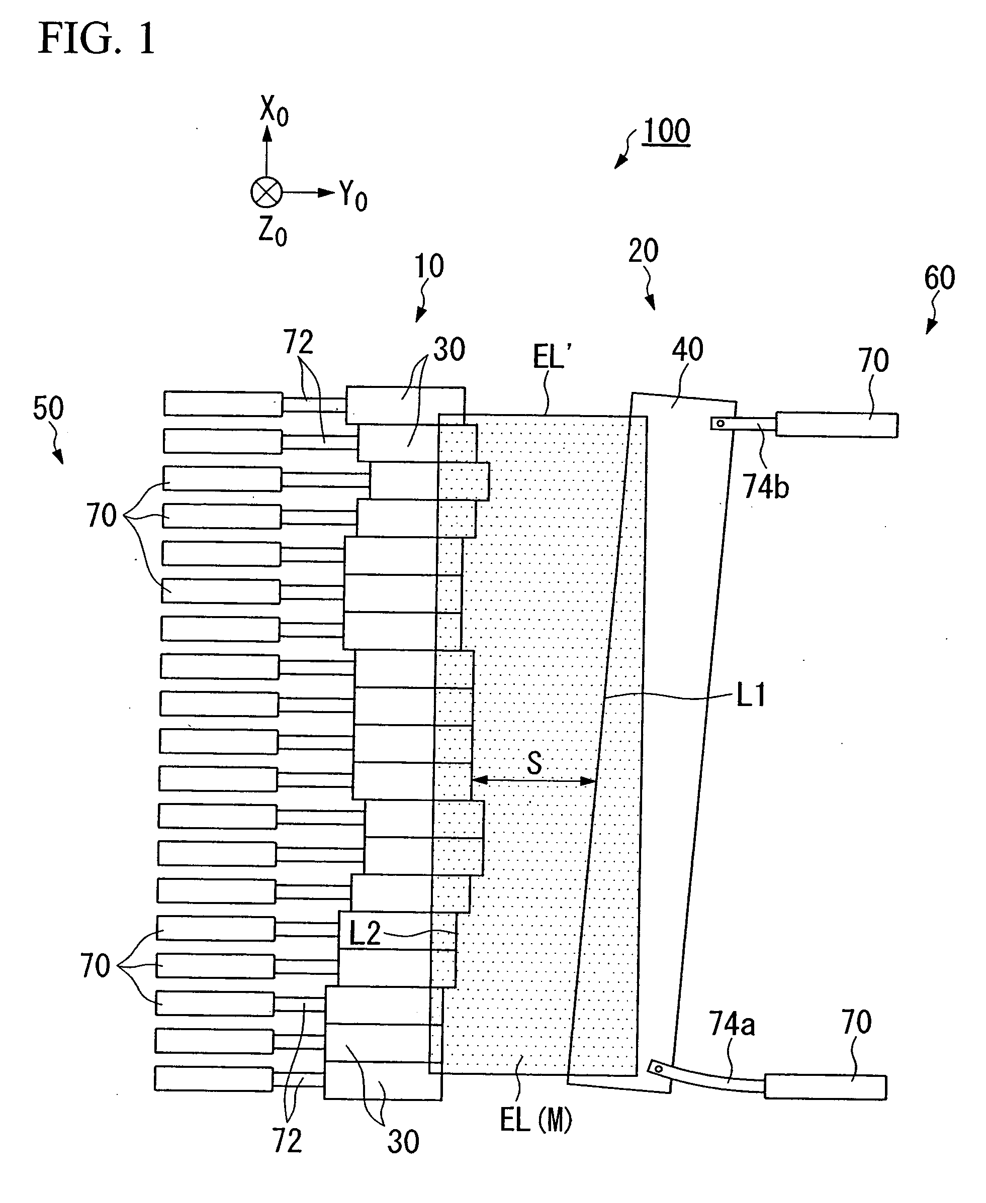
[0045] The following explains an embodiment of a variable slit apparatus of the present invention, referencing the drawings. FIG. 1 shows a variable slit apparatus 100.

[0046] First, an illumination light emitted from a light source (not shown) passes through a shaping optical system, and then is shaped into a rectangular illumination light EL′.

[0047] Furthermore, the variable slit apparatus 100 modifies the width of the rectangularly shaped illumination light EL′ in a direction (hereinafter called the latitudinal direction) substantially orthogonal to the longitudinal direction, and thereby forms a slit-shaped illumination light EL that has the desired slit width. The variable slit apparatus 100 comprises: a first light-shielding mechanism 10, which shields part of the illumination light EL that passes through the variable slit apparatus 100, for the purpose of defining one long side L2 of the slit-shaped illumination light EL; a second light-shielding mechanism 20, which shields ...


PUM


Abstract

The present invention provides a variable slit apparatus, which can rapidly change the shape of the slit width of the illumination light while finely controlling the shape of the slit-shaped illumination light, an illumination apparatus that uses such, an exposure apparatus, and the like. The variable slit apparatus for forming a slit-shaped illumination light comprises: a first light-shielding mechanism that comprises a plurality of blades for defining one long side of the illumination light; a second light-mechanism configured to define another long side of the illumination light; and a drive mechanism that changes the width of the illumination light in the latitudinal direction orthogonal to the longitudinal direction by driving the first light-shielding mechanism and the second light-shielding mechanism.

Description

CROSS-REFERENCE TO RELATED APPLICATIONS [0001] This is a Continuation Application of International Application No. PCT / JP2004 / 016885 filed Nov. 12, 2004, which claims priority to 2003-383880 filed Nov. 13, 2003. The contents of the aforementioned applications are incorporated herein by reference.BACKGROUND OF THE INVENTION [0002] 1. Field of the Invention [0003] The present invention relates to an exposure apparatus, which is used in a photolithographic process that manufactures devices like semiconductor devices, as well as to an exposure method and the like. [0004] 2. Description of Related Art [0005] In a photolithographic process that manufactures devices, such as semiconductor devices, thin film magnetic heads, and liquid crystal display devices, an exposure apparatus is generally used to transfer an image of a pattern formed on a photomask or a reticle onto a substrate, which is coated with a photosensitive agent, such as a photoresist. As the capacity of semiconductor memory ...

Claims


Application Information

Patent Timeline
IPC IPC(8): F21S8/00G03F7/20H01L21/027
CPCG03F7/70066G03F7/70558G03F7/70191
Inventor OHYA, EIZONAKAMURA, KYOJIMIZUNO, YASUSHI
Owner NIKON CORP
Why Eureka
Try Eureka