
Interlaminar tensile reinforcement of SiC/SiC CMC's using fugitive fibers

Active Publication Date: 2006-12-21
GENERAL ELECTRIC CO
View PDF31 Cites 39 Cited by
  • Summary
  • Abstract
  • Description
  • Claims
  • Application Information

AI Technical Summary

Benefits of technology

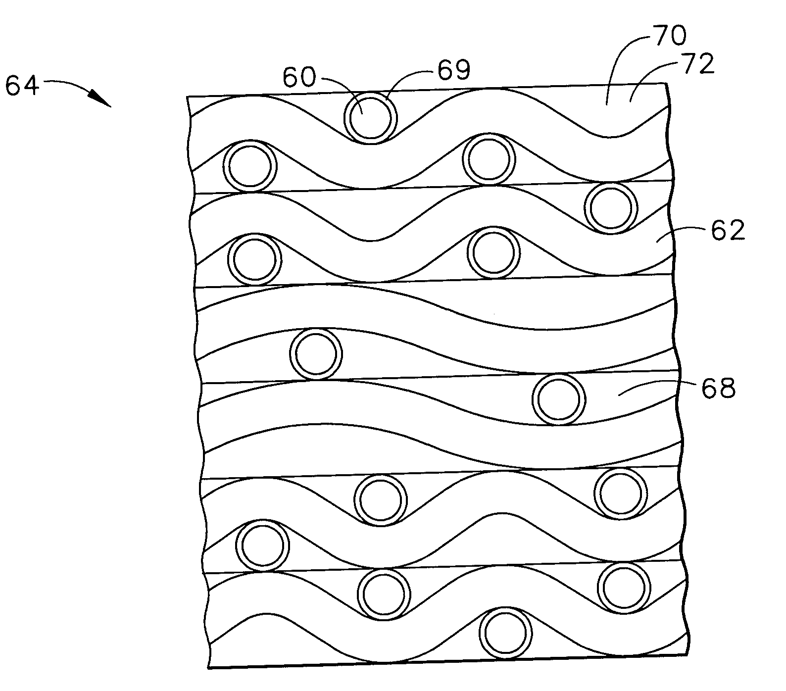
[0013] An advantage of the present invention is that a matrix rich region results that interrupts the proximity of the weaker fiber-matrix interfaces leading to improved mechanical properties and improved fracture toughness of the composite.
[0014] Another advantage of the present invention is that fugitive fibers can easily be incorporated into the weave and then burned off to create a ceramic weave having fugitive fiber void regions that are filled with ceramic material during subsequent manufacturing operations to provide the matrix rich regions in the composite.
[0015] Another advantage of the present invention is that the matrix rich regions of the composite arrests crack propagation which might otherwise follow the interface of the matrix and fibers of the ceramic weave.

Problems solved by technology

However, such materials have inherently low interlaminar properties.
In many of the hot section applications, such as combustor liners, high pressure turbine blades, high pressure turbine vanes, low pressure turbine (LPT) blades and low pressure turbine vanes, the thermal gradients and mechanical loads that result from normal engine operation result in significant local interlaminar stresses.
A major challenge in this approach is the low interlaminar strength between the interface of the fibers with the ceramic matrix.
The low interlaminar strength diminishes the ability of the CMC component to endure significant local interlaminar stresses.
However, these methods substantially reduce in-plane mechanical properties and result in significant increases in fiber preforming costs.

Method used


Image

  • Interlaminar tensile reinforcement of SiC/SiC CMC's using fugitive fibers
  • Interlaminar tensile reinforcement of SiC/SiC CMC's using fugitive fibers
  • Interlaminar tensile reinforcement of SiC/SiC CMC's using fugitive fibers

Examples


Embodiment Construction

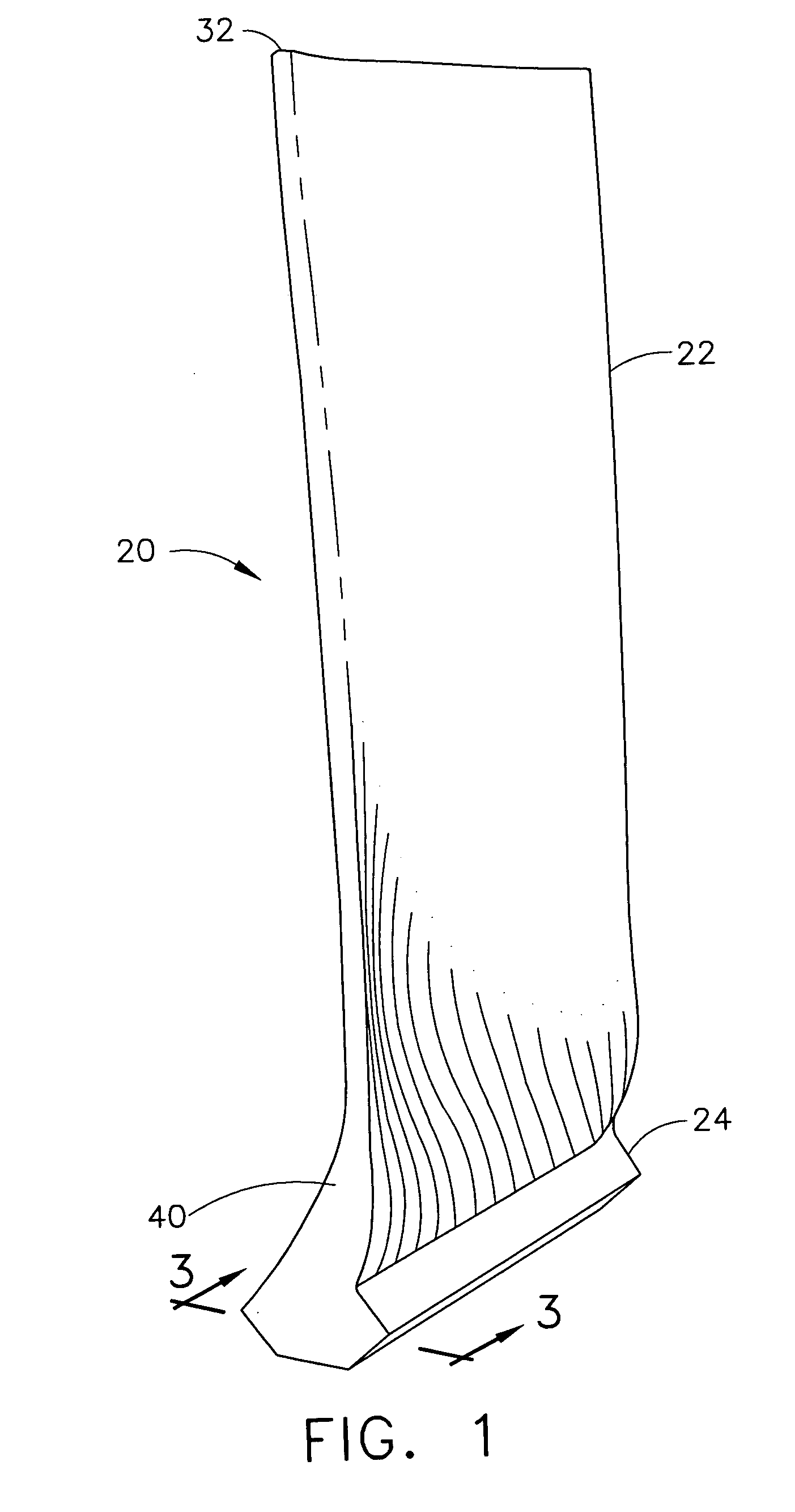
[0026]FIG. 1 depicts an exemplary aircraft engine LPT blade 20. In this illustration a turbine blade 20 comprises a ceramic matrix composite material. The turbine blade 20 includes an airfoil 22 against which the flow of hot exhaust gas is directed. The turbine blade 20 is mounted to a turbine disk (not shown) by a dovetail 24 that extends downwardly from the airfoil 22 and engages a slot of similar geometry on the turbine disk. The LPT blade 20 made according to methods of the present invention typically includes an integral platform (not shown) between the dovetail 24 and the airfoil. A separate platform which not an important aspect of the method of the present invention, is provided to minimize the exposure of the dovetail 24 to hot gases of combustion. The airfoil may be described as having a root end 40, and an oppositely disposed tip end 32.

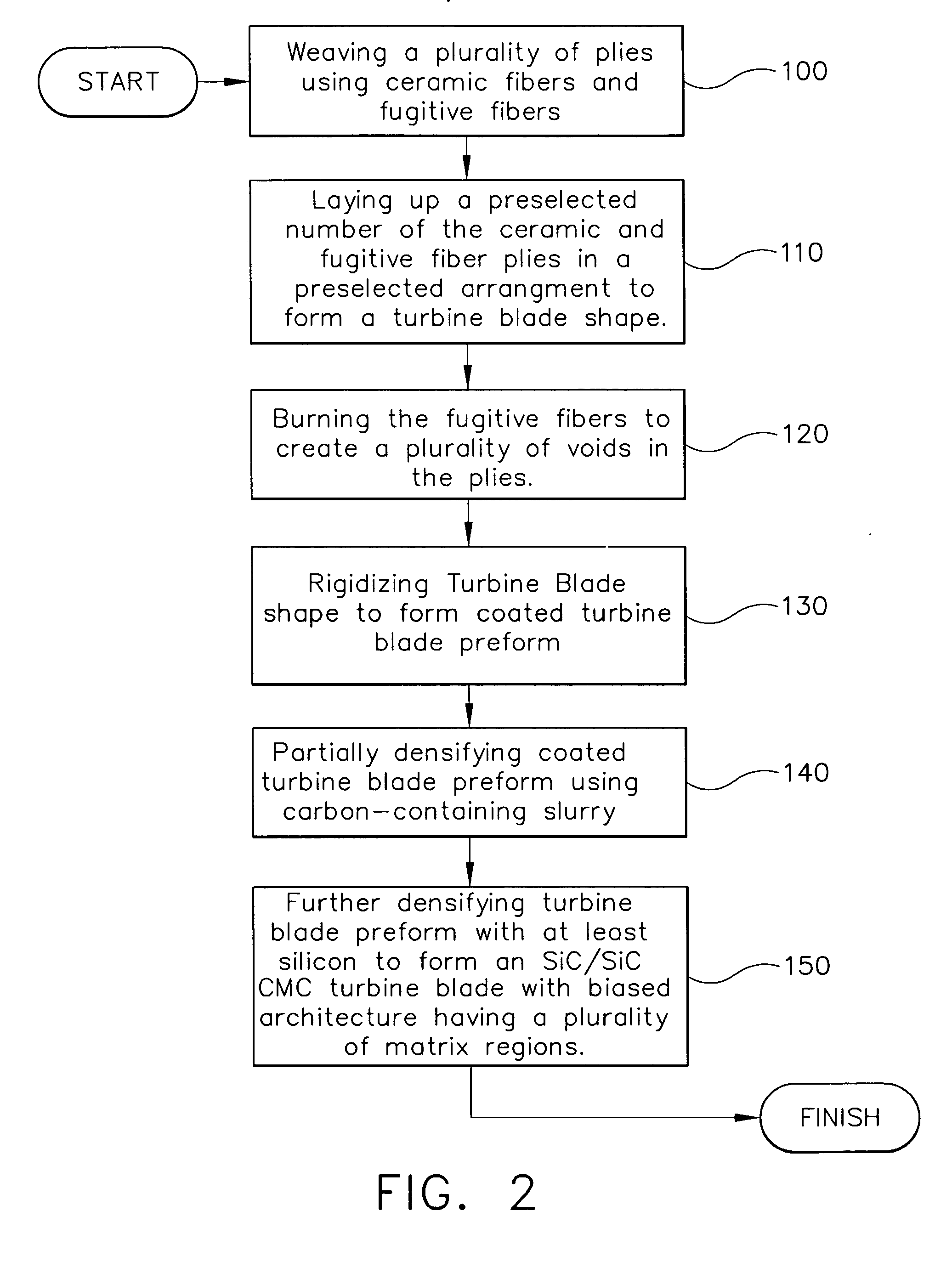
[0027] Referring now to FIG. 2 there is shown a flow chart illustrating a slurry cast MI method of manufacture of the present invention ...


PUM

PropertyMeasurementUnit
Temperatureaaaaaaaaaa
Ratioaaaaaaaaaa

Abstract

A method of manufacturing a turbine engine component is disclosed. The method includes the steps of providing a plurality of ceramic cloth plies, each ply having woven ceramic fiber tows and at least one fugitive fiber tow, laying up the plurality of plies in a preselected arrangement to form a turbine engine component shape, oxidizing the fugitive fibers to produce fugitive fiber void regions in the ply, rigidizing the component shape to form a coated component preform using chemical vapor infiltration, partially densifying the coated component preform using carbon-containing slurry, and further densifying the coated component preform with at least silicon to form a ceramic matrix composite turbine engine component having matrix rich regions.

Description

RELATED APPLICATIONS [0001] This Application is related to Application No. ______, Attorney Docket No. 121498 (07783-0161-01), filed on even date with this Application on ______, entitled “THROUGH THICKNESS REINFORCEMENT OF SiC / SiC CMC's THROUGH IN-SITU MATRIX PLUGS MANUFACTURED BY T-FORMING USING FUGITIVE FIBERS” which is also assigned to the assignee of the present invention and which is hereby incorporated by reference in its entiretySTATEMENT REGARDING FEDERALLY SPONSORED RESEARCH OR DEVELOPMENT [0002] The United States Government retains license rights in this invention and the right in limited circumstances to require the patent owner to license others on reasonable terms by the terms of Government Contract No. N00421-00-3-0536 awarded by the Department of the Navy.FIELD OF THE INVENTION [0003] The present invention relates generally to ceramic matrix turbine engine components, and more particularly, to a ceramic matrix composite turbine blade. BACKGROUND OF THE INVENTION [000...

Claims


Application Information

Patent Timeline
IPC IPC(8): D02G1/20D02J1/22B32B37/00
CPCC04B35/573Y10T29/49337C04B38/065C04B2111/00982C04B2235/5212C04B2235/5244C04B2235/5252C04B2235/5256C04B2235/5268C04B2235/616D04H13/002F01D5/28Y02T50/67Y02T50/672C04B35/806F05D2300/222F05D2300/603F05D2300/224F05D2300/6012F05D2300/601C04B38/067C04B38/0675C04B35/62868C04B35/62873C04B35/80Y02T50/60
Inventor SUBRAMANIAN, SURESHSTEIBEL, JAMES DALECARPER, DOUGLAS MELTON
Owner GENERAL ELECTRIC CO
Learn More