
Optically-pumped vertical external cavity surface emitting laser

a laser and external cavity technology, applied in lasers, laser cooling arrangements, laser details, etc., can solve the problems of increasing the size of the heat spread, difficult to align the entire components of the vecsel, increasing the manufacturing cost, etc., and achieves easy alignment and increase oscillation efficiency

Inactive Publication Date: 2006-12-14
SAMSUNG ELECTRONICS CO LTD
View PDF10 Cites 11 Cited by
  • Summary
  • Abstract
  • Description
  • Claims
  • Application Information

AI Technical Summary

Benefits of technology

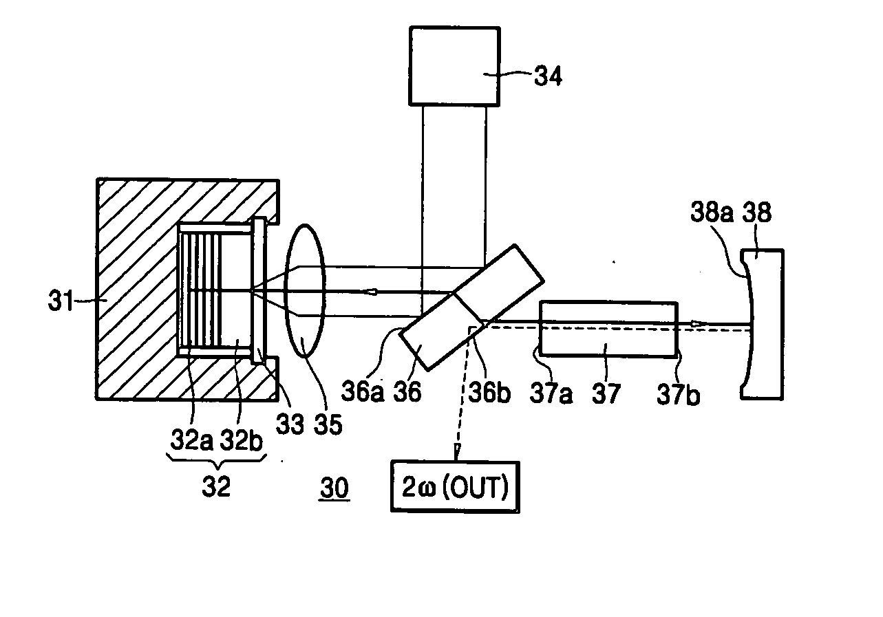
[0013] The present invention provides a VECSEL that is designed to make a pump laser beam incident a laser chip at a right angle to increase oscillation efficiency and allow easy alignment.
[0014] The present invention also provides a VECSEL that is designed to focus a light beam generated from a laser chip onto an SHG crystal to increase the optical converting efficiency of the SHG crystal.

Problems solved by technology

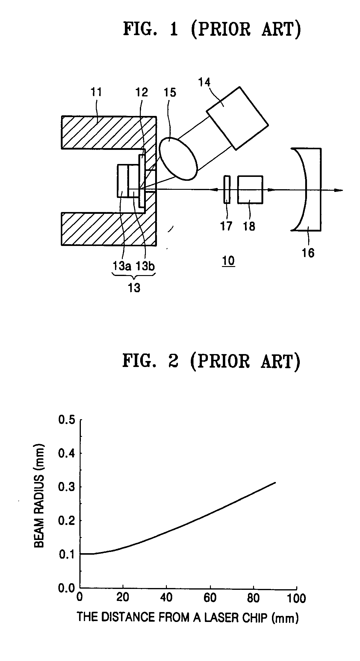
However, according to the aforementioned conventional VECSEL 10, the pump laser 14 used for activating of the laser chip 13 is diagonally disposed, thereby making it difficult to align the entire components of the VECSEL 10.
This increases the size of the heat spread 12 and thereby increases the manufacturing cost.
However, the SHG crystal 18 cannot be disposed close to the laser chip 13 because of the filter 17 and the pump laser 14, thereby decreasing the efficiency of the SHG crystal 18.
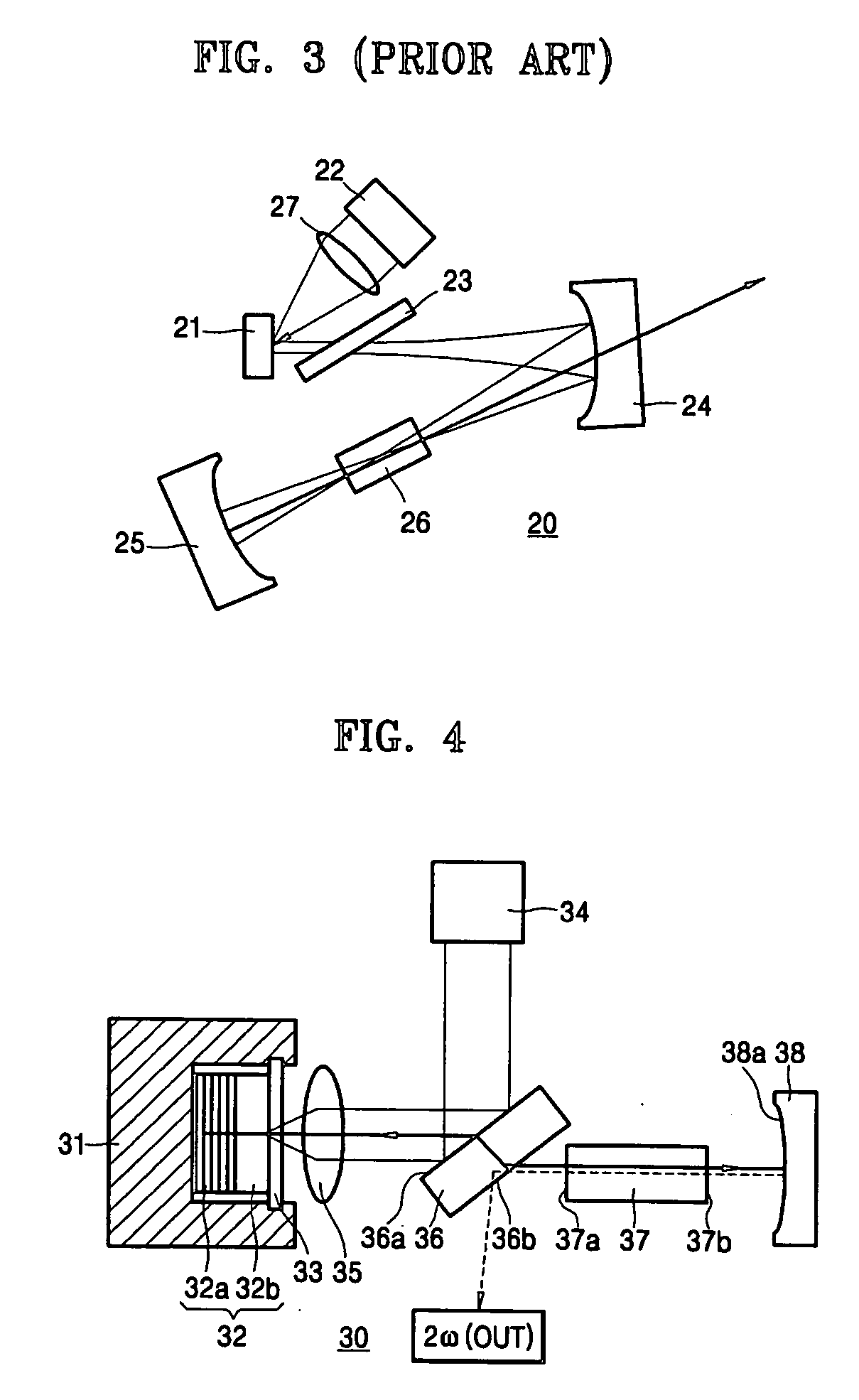
However, the conventional VECSEL 20 requires an additional external mirror, and also it is difficult to align the two external mirrors because the external mirrors must be diagonally arranged.
Therefore, the overall size of the laser system becomes larger.
Further, the VECSEL 20 has another disadvantage of outputting a laser beam at an angle.
In addition, the aforementioned problems resulting from diagonal arrangement of a pump laser 22 and a lens 27 are not resolved.

Method used


Image

  • Optically-pumped vertical external cavity surface emitting laser
  • Optically-pumped vertical external cavity surface emitting laser
  • Optically-pumped vertical external cavity surface emitting laser

Examples


Embodiment Construction

[0034]FIG. 4 is a sectional view of a VECSEL according to an embodiment of the present invention. Referring to FIG. 4, a laser chip 32 may be loaded on a heat sink 31, and a transparent heat spreader 33 may be disposed on the laser chip 32. The heat spreader 33 transfers heat generated from the laser chip 32 to the heat sink 31 to dissipate the heat to the outside, and for this purpose, the heat spreader 33 is formed of material having a high optical transmittance and thermal conductivity such as diamond. In a VECSEL 30 of an embodiment of the present invention, the laser chip 32 is activated by optical pumping to emit light at a first wavelength. As known to those of ordinary skill in the art, the laser chip 32 includes a DBR layer 32a and an active layer 32b that are sequentially stacked. The active layer 32b, for example, has a multi quantum well structure, and it is exited by pump light to emit light at a predetermined wavelength.

[0035] An external mirror 38 is spaced apart fro...


PUM


Abstract

A vertical external cavity surface emitting laser (VECSEL) is provided in which a pump laser beam is incident on a laser chip at a right angle. In the surface emitting laser, a laser chip emits light at a first wavelength by optical pumping, an external mirror is spaced apart from the laser chip to reflect the first wavelength light emitted from the laser chip back to the laser chip, a pump laser emits light at a second wavelength to cause the laser chip to lase, a wavelength selecting mirror is disposed between the laser chip and the external mirror to reflect the second wavelength light emitted from pump laser to the laser chip and to transmit the first wavelength light emitted from the laser chip, and an optical unit is disposed between the wavelength selecting mirror and the laser chip to focus the first wavelength light on an optical path between the external mirror and the wavelength selecting mirror and to focus the second wavelength light on the laser chip.

Description

CROSS-REFERENCE TO RELATED PATENT APPLICATION [0001] This application claims the benefit of Korean Patent Application No. 10-2005-0048859, filed on Jun. 8, 2005, in the Korean Intellectual Property Office, the disclosure of which is incorporated herein in its entirety by reference. BACKGROUND OF THE DISCLOSURE [0002] 1. Field of the Disclosure [0003] The present disclosure relates to an optically-pumped surface emitting laser, and more particularly, to a vertical external cavity surface emitting laser (VECSEL) in which a pump laser beam is incident on a laser chip at a right angle. [0004] 2. Description of the Related Art [0005] A VECSEL is a laser device that has a gain region increased by replacing an upper mirror of a vertical cavity surface emitting laser (VCSEL) with an external mirror to obtain a high output power in the range of several to several tens of wafts or more. [0006]FIG. 1 is a schematic sectional view of a conventional optically-pumped VECSEL. Referring to FIG. 1, ...

Claims


Application Information

Patent Timeline
IPC IPC(8): H01S3/04H01S3/10H01S5/00H01S3/091H01S3/08H01S3/092
CPCH01S3/109H01S5/02484H01S5/183H01S5/141H01S5/041
Inventor YOO, JAE-RYUNG
Owner SAMSUNG ELECTRONICS CO LTD
Learn More