
High and low refractive index and metallic surface relief coatings

a technology of refractive index and metallic surface, applied in coatings, printing, natural mineral layered products, etc., can solve the problems of inability to emboss or cast in localized regions, and inability to achieve embossing or casting

Inactive Publication Date: 2006-12-07
HOLOINKS
View PDF14 Cites 32 Cited by
  • Summary
  • Abstract
  • Description
  • Claims
  • Application Information

AI Technical Summary

Benefits of technology

[0018] The present invention provides articles comprising a substrate, a high (or low) refractive index and / or metallic surface relief coating that is applied to the substrate and surface relief structures that are applied to the coating at substantially the same speeds and widths of conventional printing systems, and in substantially perfect register to conventional printing systems, thereby obviating the need for already-embossed substrates including films and hot-stamping and cold-stamping foils.

Problems solved by technology

These embossing and casting processes suffer from a number of known drawbacks, including: (1) the processes are not suitable for use with the printing equipment; (2) embossing or casting in localized regions is not possible with conventional metallizing equipment; (3) the metallizing equipment is prohibitively expensive; (4) printing onto the embossed and metallized material is very slow and expensive; (5) conventional embossing and casting systems are much slower than printing equipment; (6) it is difficult to overprint onto a holographic substrate when perfect registration is required; (7) holographic substrates may cover the entire face of the substrate, which may be a problem if the final product is a label, package or security document; and (8) holographic hot-stamping and cold-stamping substrates may have to be added to the printing in attachments placed on the conventional printing equipment.
However, such systems have failed due to the difficulty of maintaining a proper vacuum for aluminum deposition in a printing process that requires an air-to-air vacuum metallizer.
Additionally, these systems are very complex and expensive, and require at least two additional steps including curing the hologram and metallizing the hologram.
However, such processes often result in surface relief distortions.
One drawback of reflective surface reliefs is that the quality of the metallic ink may not be as reflective as desired because the metallic particles that are mixed into the pigment do not properly align themselves according to the planar features of the substrate and the surface relief.
This results in a dulling of the surface relief image and leafing problems that require the application of a protective coating.
Another drawback of reflective surface reliefs is that the thickness of the metallic coating diminishes the holographic effect.
This relatively thick coating tends to obliterate the brightness and efficiency of the surface relief.
However, the methods disclosed by these references suffer from a number of drawbacks.
Both post metallization and the application of a reflective coating are slow and expensive processes.
A further drawback of the above-identified Spanish patents is that they require a 360-degree holographic cylinder.
Moreover, there is no disclosure regarding the use of different coatings having different refractive indexes for producing bright and viewable holography.
One drawback of this patent is that the method of the invention requires two or more curing steps to cure the lacquer.
Additionally, the post-curing step may create problems in the resolution of the surface features because the features will start to degrade as soon as the substrate leaves the molding station until they are 100% cured.
A further drawback is that the invention does not envision the use of metallic inks and lacquers to make the structures reflective without the use of expensive vacuum metallizing equipment.
Another drawback of the above-identified European patent is that it does not disclose the use of high and low diffractive index transparent inks and lacquers in order to avoid rendering the structure invisible when it is overprinted or overlaminated.
An additional drawback is that the device of the invention is based on old-fashioned gear systems rather than contemporary gearless devices.
Yet another drawback is that the preferred molding material is a transparent elastomer made of Polydimetylsiloxane (PDMS), which degrades quickly with electromagnetic radiation.
Some drawbacks of this reference are that: (1) it does not disclose the use of a high refractive layer; (2) the base substrate is metallic; (3) it involves printing in layers rather than printing in register; and (4) it does not involve applying selective holography.
One drawback of conventional coatings is that they require an expensive multi-step process in order to make the surface relief structures viewable.
Particularly, the process may comprise the steps of: (1) applying the coating to a substrate on a coating machine; (2) embossing the coating; and (3) vacuum metallizing or sputtering using prohibitively expensive equipment.
However, these surface relief structures still require the use of the expensive metallizing or sputtering equipment with different coatings containing deposited metals such as aluminum, silver, gold, cobalt, nickel, chromium, and / or other suitable metals.
Another drawback of conventional coating, sputtering, and metallizing techniques concerns the difficulty of producing selective areas that are metallized while leaving the surrounding areas with no metal.
A further drawback involves a lack of registration between these techniques and conventional printing processes.
This multi-step process is both prohibitively expensive and extremely slow.

Method used


Image

  • High and low refractive index and metallic surface relief coatings
  • High and low refractive index and metallic surface relief coatings
  • High and low refractive index and metallic surface relief coatings

Examples


Embodiment Construction

[0036] In the following paragraphs, the present invention will be described in detail by way of example with reference to the attached drawings. Throughout this description, the preferred embodiment and examples shown should be considered as exemplars, rather than as limitations on the present invention. As used herein, the “present invention” refers to any one of the embodiments of the invention described herein, and any equivalents. Furthermore, reference to various feature(s) of the “present invention” throughout this document does not mean that all claimed embodiments or methods must include the referenced feature(s).

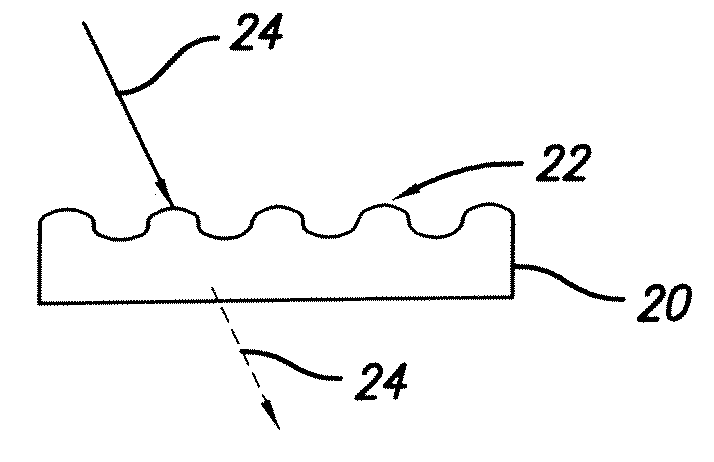
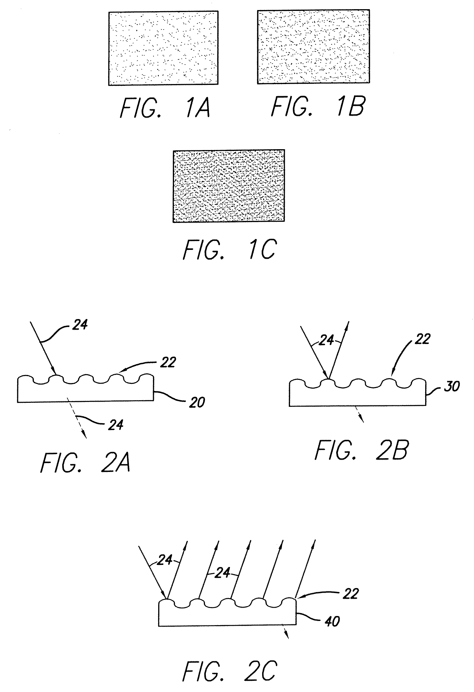
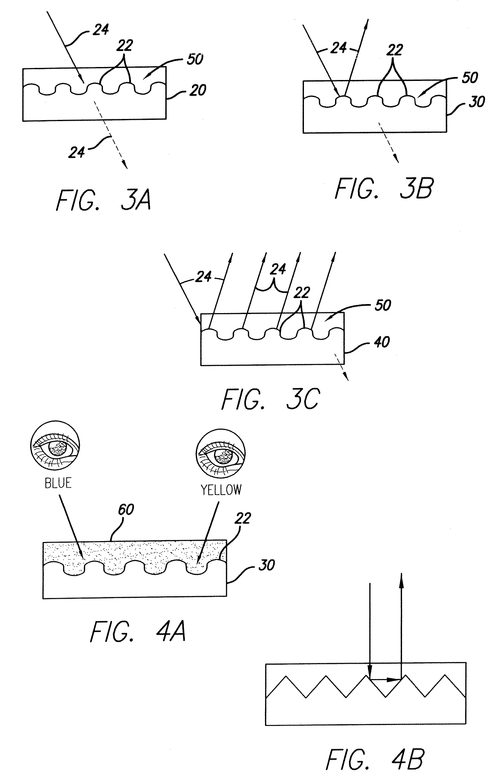
[0037] The present invention is directed to nano-, micro-, and macro- surface relief structures featuring high refractive index surface relief (HRISR) coatings, low refractive index surface relief (LRISR) coatings, metallic inks and / or lacquers for surface relief structures that are “printed” or cast (cured) in conventional or digital printing equipment with perfec...


PUM

PropertyMeasurementUnit
depthaaaaaaaaaa
depthaaaaaaaaaa
thicknessaaaaaaaaaa

Abstract

The present invention provides articles comprising a substrate, a high (or low) refractive index and / or metallic surface relief coating that is applied to the substrate and surface relief structures that are applied to the coating at substantially the same speeds and widths of conventional printing systems, and in substantially perfect register to conventional printing systems, thereby obviating the need for already-embossed substrates including films and hot-stamping foils.

Description

REFERENCE TO RELATED APPLICATIONS [0001] This application is a Continuation-In-Part of U.S. patent application Ser. No. 11 / 144,349, filed Jun. 3, 2005.FIELD OF THE INVENTION [0002] The present invention is directed to surface relief structures, and more particularly to, high and low refractive index and metallic surface relief coatings that are applied using conventional printing equipment. BACKGROUND OF THE INVENTION [0003] Conventional holographic surface reliefs are manufactured by slow embossing and casting processes that are separate from mainstream printing processes. For example, the processes may involve embossing onto pre-metallized materials or casting onto clear films and papers, and then metallizing the embossed materials. These embossing and casting processes suffer from a number of known drawbacks, including: (1) the processes are not suitable for use with the printing equipment; (2) embossing or casting in localized regions is not possible with conventional metallizin...

Claims


Application Information

Patent Timeline
Patent Type & Authority Applications(United States)
IPC IPC(8): B32B9/00B32B19/00C09D7/61
CPCB41F5/22B41F5/24B41F13/22B41F19/062B41F31/002B41P2200/12B41P2213/734C08K3/08C08K3/14C08K3/22C08K3/28C09D5/004C09D5/29B42D25/328C09D7/61
Inventor LIEBERMAN, DANIEL
Owner HOLOINKS
Learn More