
Method and system integrating solar heat into a regenerative rankine steam cycle

a solar heat and rankine steam technology, applied in the field of electric power generation, can solve the problems of high entropic loss, inapplicability to rankine steam cycles, expensive solar boilers, etc., and achieve the effect of improving solar system efficiency

Inactive Publication Date: 2006-11-30
MARKRON TECH
View PDF11 Cites 87 Cited by
  • Summary
  • Abstract
  • Description
  • Claims
  • Application Information

AI Technical Summary

Benefits of technology

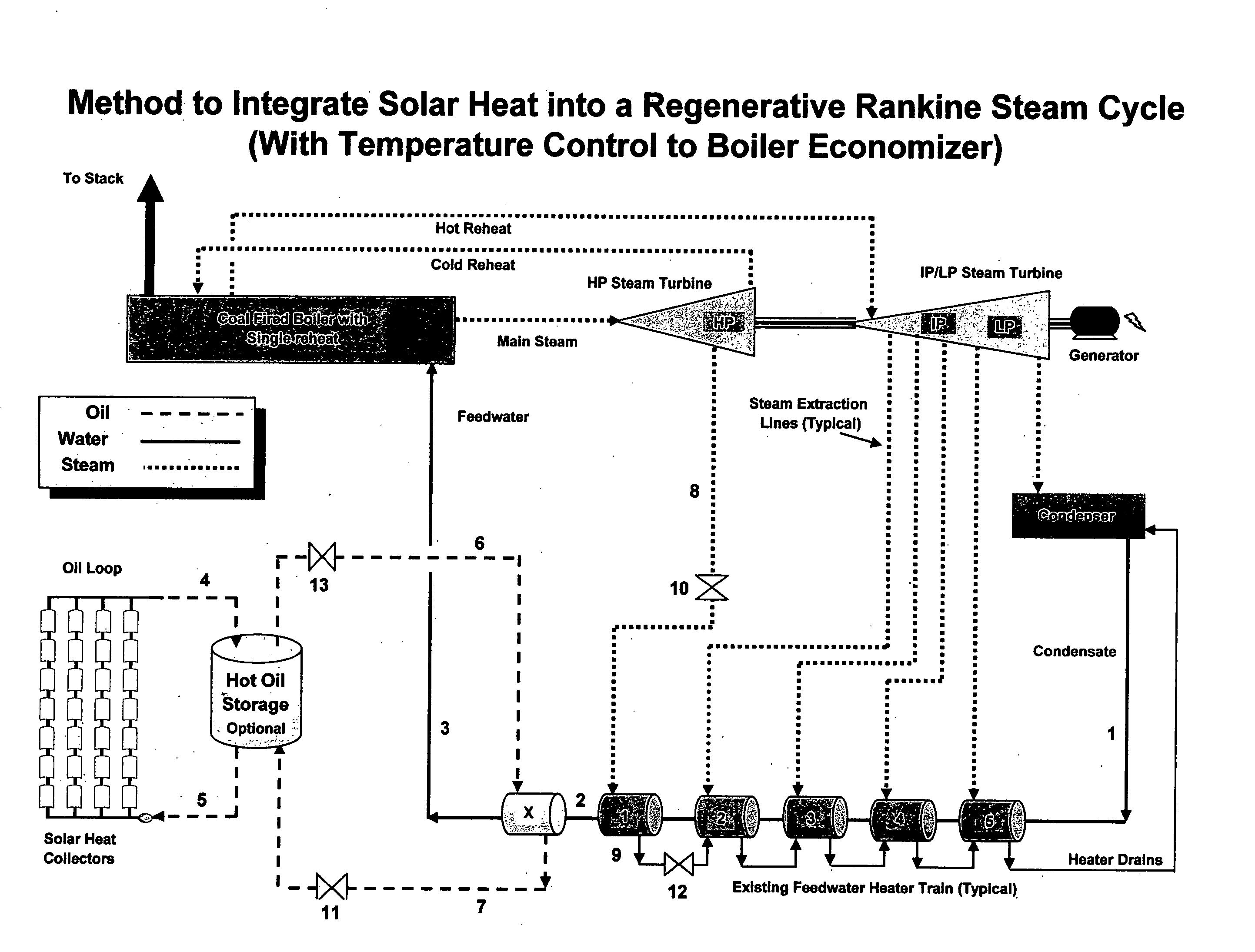
[0012] It is noted that all of the feedwater heating in the proposed concept is provided by solar sensible heat. Accordingly, there is higher solar system efficiency since no heat of evaporation (latent heat) is solar provided; this allows heat transfer with smaller temperature differences than otherwise would be realized if the solar heat was used for evaporation also. The heat of evaporation for the Rankine cycle occurs in the fossil fueled boiler and, consequently, entropic losses associated with this flashing are already accounted for in the fossil fueled Rankine cycle. The use of solar provided sensible heat to an existing Rankine cycle is an advantage compared to a solar cycle which must provide its own latent heat for flashing.

Problems solved by technology

This method would then require an expensive solar boiler and is not applicable to a Rankine cycle using regenerative heating.
Warren U.S. Pat. No. 4,069,674 teaches that the feedwater is bifurcated immediately at the condenser hotwell resulting in high temperature solar being used to heat relatively cold feedwater resulting in high entropic losses.
This type of technology results in complex and costly equipment when compared to the novelty proposed.
While all of these methods provide some sort of value addition, they all have certain thermodynamic restrictions and cost disadvantages.

Method used


Image

  • Method and system integrating solar heat into a regenerative rankine steam cycle
  • Method and system integrating solar heat into a regenerative rankine steam cycle
  • Method and system integrating solar heat into a regenerative rankine steam cycle

Examples


Embodiment Construction

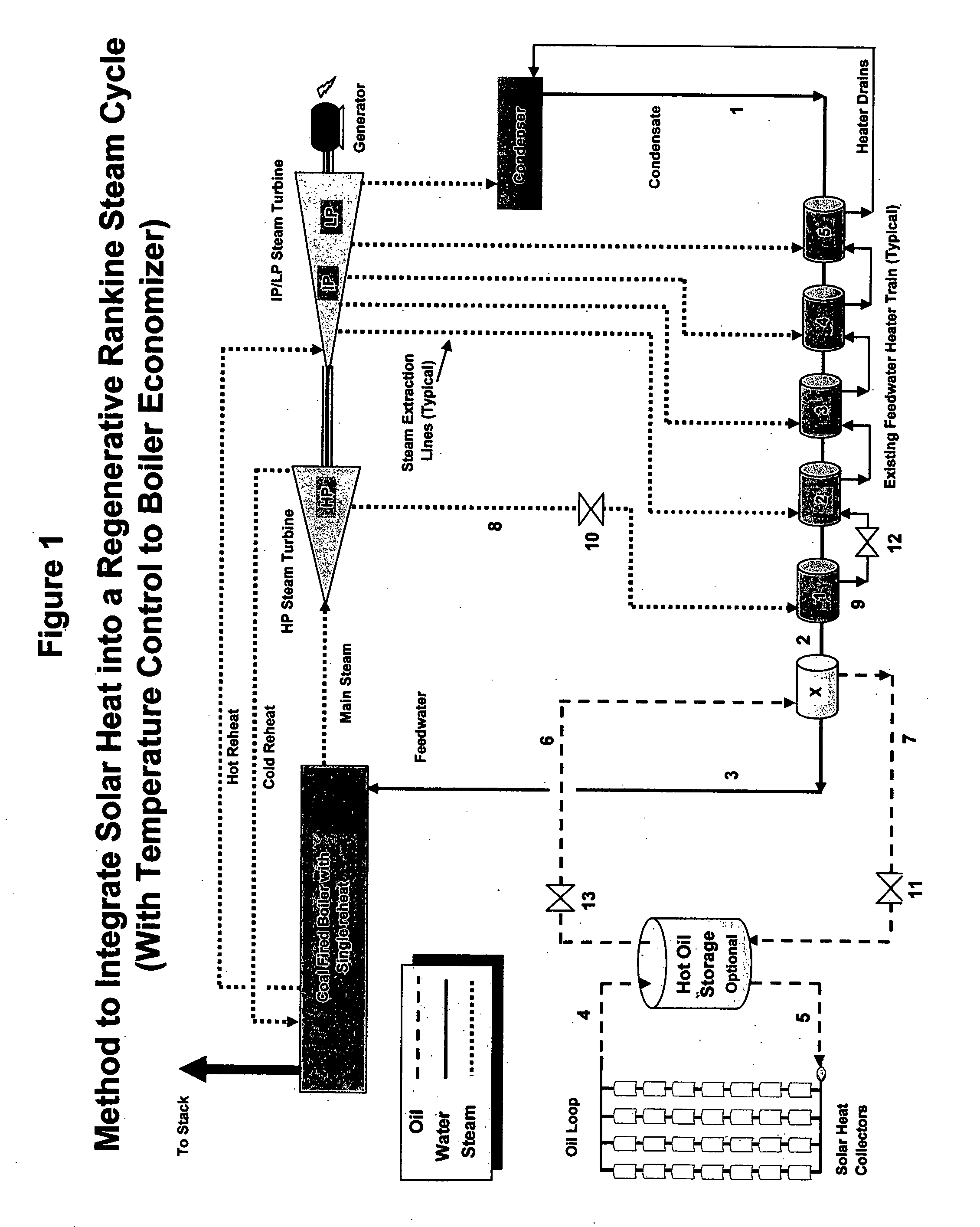
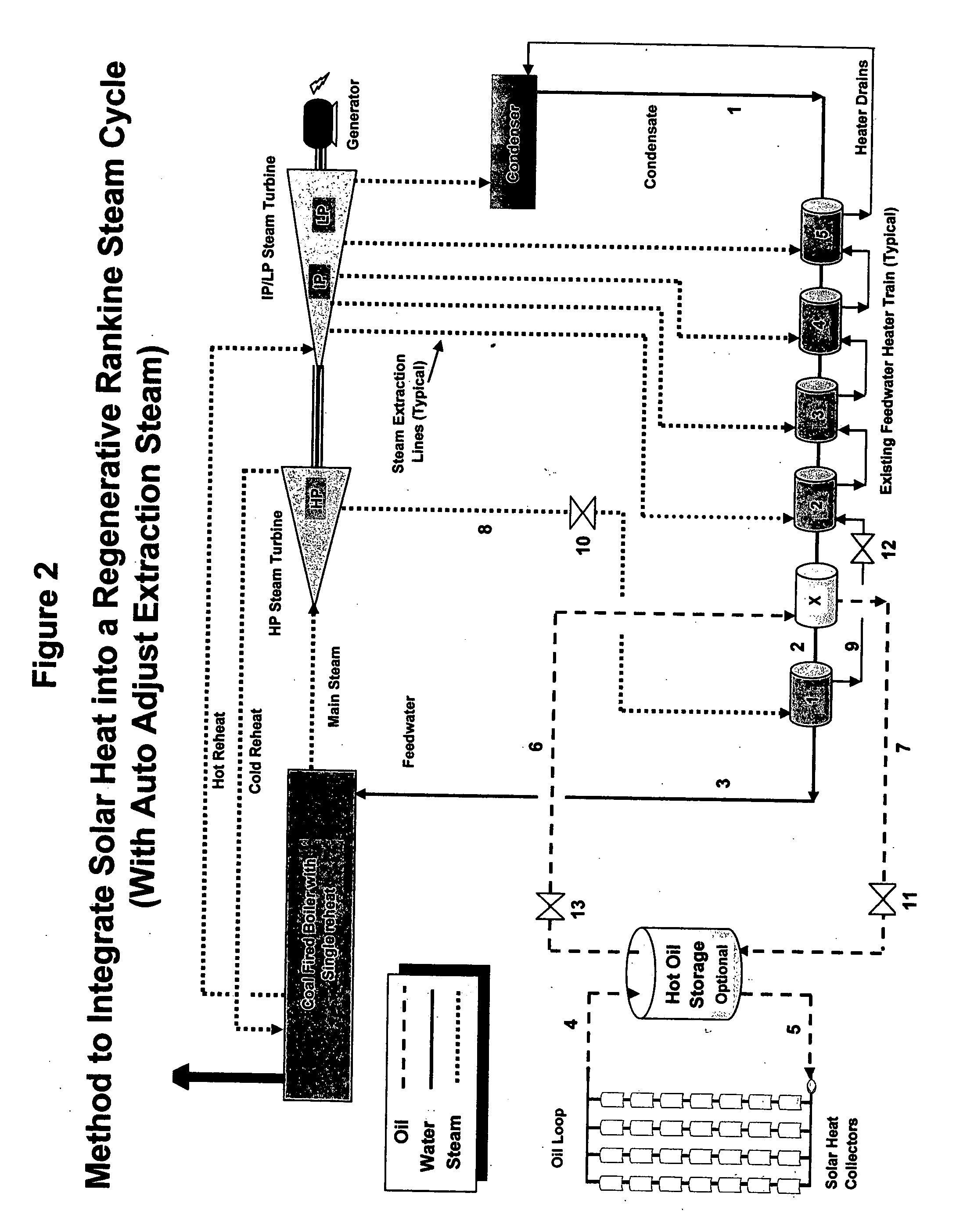
[0015] Referring to FIG. 1, solar heat is collected with trough technology or other suitable solar concentrating heat collection devices. Using the solar trough technology (which can be substituted with other high temperature solar heating devices), the sun's energy is “line” focused on a Heat Collection Element (HCE). The HCE is essentially a specially designed pipe that contains a fluid suitable for the collection of high temperature heat. Once the sun's energy has been focused and concentrated on the HCE, the energy is collected in the high temperature collection fluid 4 that is typically special oil designed to withstand high temperatures. Current technology limits this temperature to about 730-750 F. The hot oil is then pumped into a Hot Oil Storage (optional) that would provide both storage for extended operation or storage that would allow for higher outputs of thermal energy for shorter durations. The Hot Oil Storage also provides a buffer to smooth out heat spikes and heat ...


PUM


Abstract

A method to integrate collected solar thermal energy into the feedwater system of a Rankine cycle power plant is disclosed. This novelty uses a closed loop, single phase fluid system to collect both the solar heat and to provide the heat input into the feedwater stream of a regenerative Rankine cycle. One embodiment of this method of integrating solar energy into a regenerative Rankine power plant cycle, such as a coal power plant, allows for automatic balancing of the steam extraction flows and does not change the temperature of the feedwater to the boiler. The concept, depending on the application, allows for the spare turbine capacity normally available in a coal plant to be used to produce incremental capacity and energy that is powered by solar thermal energy. By “piggybacking” on the available components and infrastructure of the host Rankine cycle power plant, considerable cost savings are achieved resulting in lower solar produced electricity costs.

Description

REFERENCES CITED U.S. Patent Documents [0001]3,995,429Rollins4,069,674Warren4,192,144Pierce4,613,409Volland5,444,972Moore5,727,379Cohn5,806,317Kohler, et al5,857,322Cohn6,792,759Rollins6,694,740NayarTECHNICAL PAPERS AND PUBLICATIONS 12th SolarPACES Intern. Symposium, Mexico 2004 “Plug-In Strategy for Market Introduction of Fresnel Collectors”, Lurchenmuller et al “Stanwell Solar Thermal Power Project” by Burbidge, et al CROSS-REFERENCE TO RELATED APPLICATIONS [0002] This application claims the benefits of the U.S. Provisional Patent Application No. 60 / 684,845 entitled “Method To Integrate Solar Thermal With A Coal Fired Rankine Cycle” filed on May 27, 2005. This provisional application is incorporated by reference herein in its entirety. FIELD OF THE INVENTION [0003] This invention pertains to the electric power generation field wherein large utility size power plants are used to generate the nation's electricity. The ever increasing cost of fossil fuels will not abate since fossil...

Claims


Application Information

Patent Timeline
IPC IPC(8): F03G6/00B60L8/00B60K16/00
CPCF01K3/18Y02E10/46F05B2220/301F03G6/005Y02T10/7072
Inventor SKOWRONSKI, MARK JOSEPHKINCAID, RONALD FARRIS
Owner MARKRON TECH
Learn More