
Substrate for mounting IC chip, substrate for motherboard, device for optical communication, manufacturing method of substrate for mounting IC chip, and manufacturing method of substrate for motherboard

a technology for mounting ic chips and substrates, which is applied in the direction of circuit optical details, optical elements, instruments, etc., can solve the problems of large size of the device itself and difficulty in minimizing the terminal device, so as to reduce the transmission loss, suppress the diffusion of optical signals, and transmit more effectively

Active Publication Date: 2006-11-23
IBIDEN CO LTD
View PDF7 Cites 110 Cited by
  • Summary
  • Abstract
  • Description
  • Claims
  • Application Information

AI Technical Summary

Benefits of technology

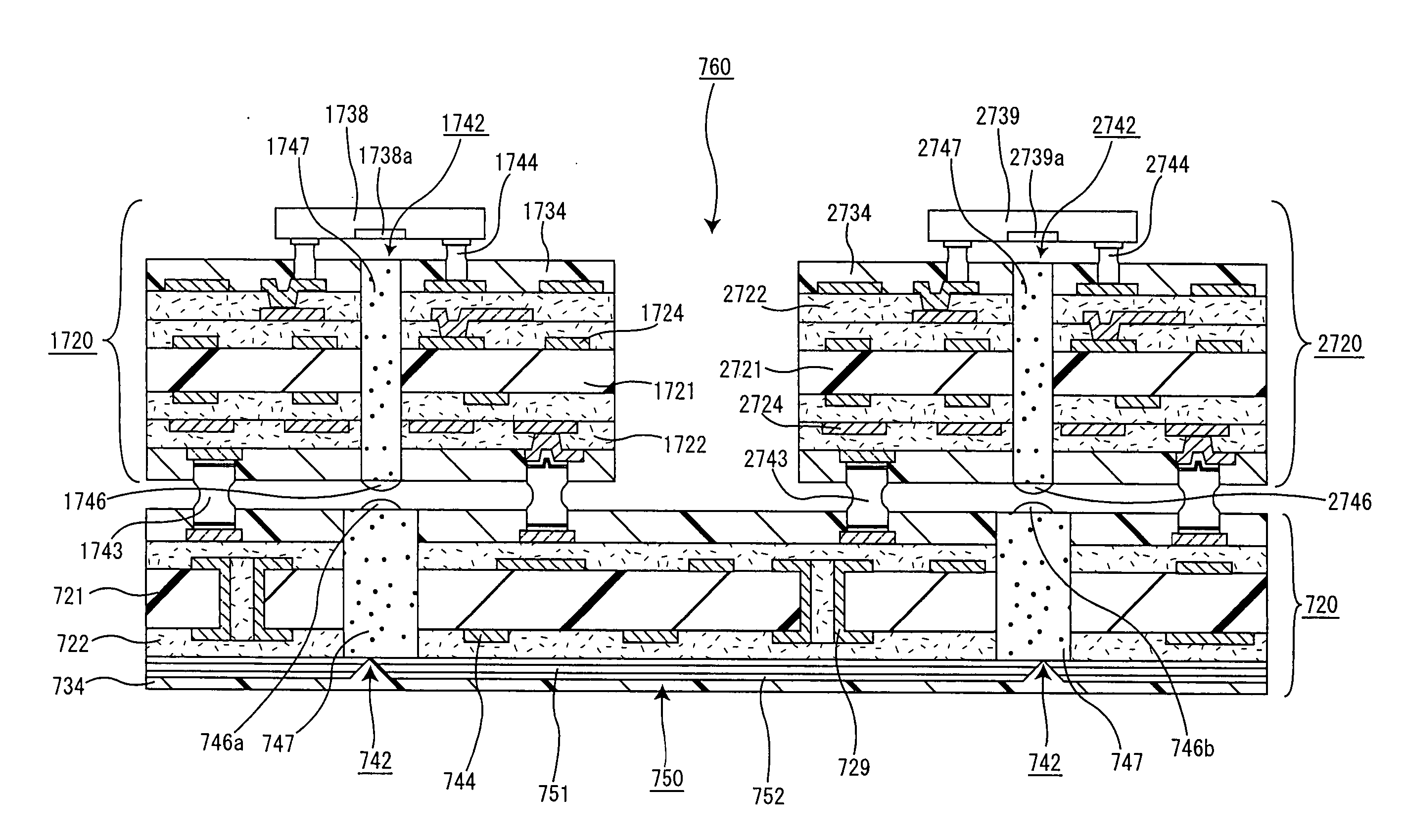
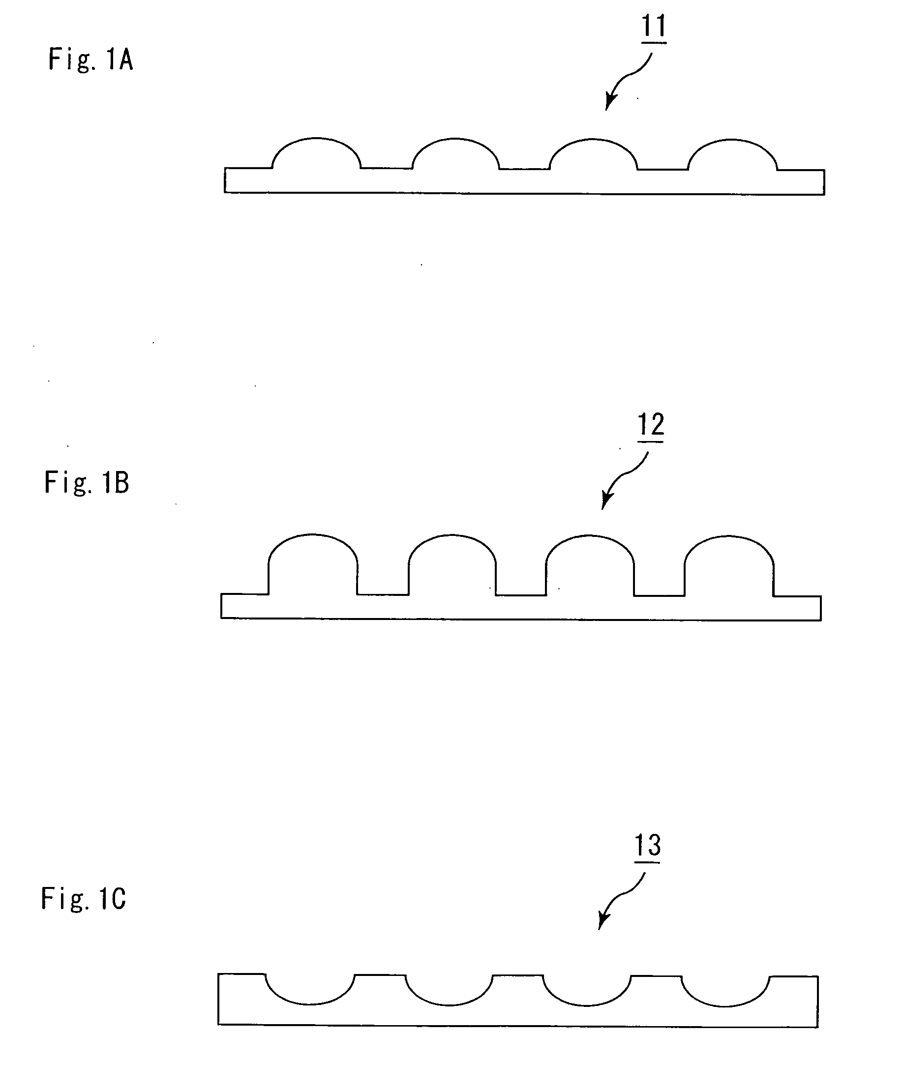
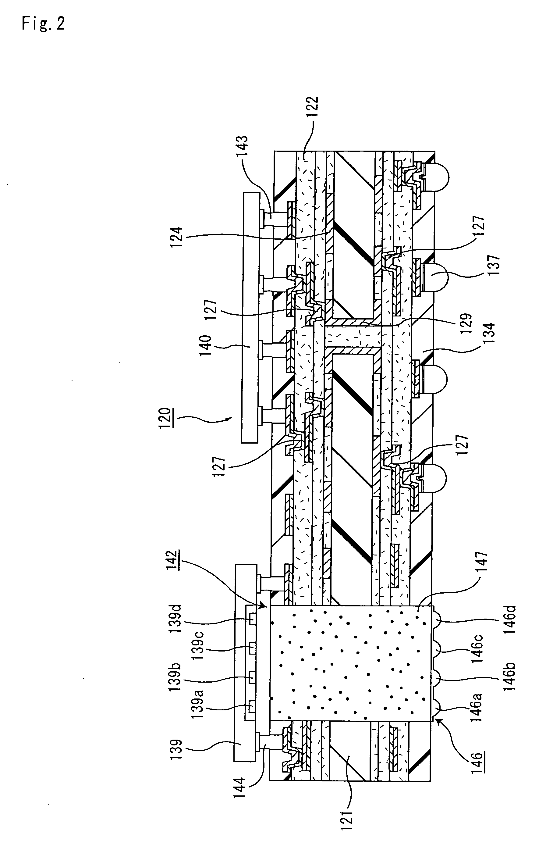
[0063] As described above, since the microlens is arranged on the end portion on the optical signal passing region in the substrate for mounting an IC chip according to the first aspect of the present invention, an optical signal that enters the light receiving element and an optical signal that is emitted from the light emitting element pass through the microlens, and thus diffusion in the optical signal can be suppressed, and input / output signals of the optical element can be transmitted more effectively. Accordingly, the loss hardly occurs in an optical signal, and a substrate for mounting an IC chip reduced of the transmission loss can be achieved.
[0064] Moreover, optical signals can be transmitted more positively between the optical element arranged on the substrate for mounting an IC chip and an optical part and the like mounted on an external substrate and the like, such as the substrate for a motherboard according to the second aspect of the present invention described later, and consequently an optical communication system with high reliability in transmission of optical signals can be achieved.
[0065] In the substrate for mounting an IC chip according to the first aspect of the present invention, input / output signals of the optical element can be transmitted via the optical signal passing region. Moreover, since the distance between the IC chip and the optical element becomes short when an IC chip is mounted on the substrate for mounting an IC chip, excellent reliability in electric signal transmission can be provided.
[0066] Moreover, since an electronic part and an optical element required for optical communication can be integrally formed in the substrate for mounting an IC chip according to the present invention, a thin and small terminal device for optical communication can be provided.
[0067] As described above, since the microlens is arranged on the end portion of the optical signal passing region in the substrate for a motherboard according to the second aspect of the present invention, an optical signal that enters an optical waveguide formed on the substrate for a motherboard and an optical signal that is emitted from the optical waveguide pass through the microlens, and thus diffusion in the optical signal can be suppressed, and input / output signals of the optical element can be transmitted more effectively. Accordingly, the loss hardly occurs in an optical signal, and a substrate for a motherboard that can reduce the transmission loss can be achieved.
[0068] Moreover, optical signals can be transmitted more positively between the optical waveguide formed on the substrate for a motherboard and an optical element and the like mounted on the substrate for mounting an IC chip and the like according to the first aspect of the present invention, and consequently an optical communication system with high reliability in transmission of optical signals can be achieved.

Problems solved by technology

When the package substrate mounted with an IC chip, the optical elements such as a light receiving element and a light emitting element and the like which processes an optical signal, and parts of the like are mounted separately on such a conventional terminal device, the size of the device itself becomes large, making it difficult to minimize the terminal device.

Method used


Image

  • Substrate for mounting IC chip, substrate for motherboard, device for optical communication, manufacturing method of substrate for mounting IC chip, and manufacturing method of substrate for motherboard
  • Substrate for mounting IC chip, substrate for motherboard, device for optical communication, manufacturing method of substrate for mounting IC chip, and manufacturing method of substrate for motherboard
  • Substrate for mounting IC chip, substrate for motherboard, device for optical communication, manufacturing method of substrate for mounting IC chip, and manufacturing method of substrate for motherboard

Examples


example 1

A. Fabrication of resin film for insulating layer

[0836] To 20 parts by weight of ethyl diglycol acetate and 20 parts by weight of solvent naphtha were added 30 parts by weight of bisphenol A-type epoxy resin (epoxy equivalent: 469, EPICOAT 1001 made by Yuka Shell Epoxy K.K.), 40 parts by weight of cresol novolak-type epoxy resin (epoxy equivalent: 215, EPICRON N-673 made by Dainippon Ink & Chemicals, Inc.) and 30 parts by weight of triazine structure-containing phenol novolak resin (phenolic hydroxide group equivalent: 120, PHENOLITE KA-7052 made by Dainippon Ink & Chemicals, Inc.) so as to be dissolved therein while being stirred under heat, and to this were further added 15 parts by weight of polybutadiene rubber with epoxidized terminals (DENAREX R-45EPT, made by Nagase Kasei Kogyo K.K.), 1.5 parts by weight of 2-phenyl-4,5-bis(hydroxymethyl) imidazole pulverized product, 2 parts by weight of fine pulverized silica and 0.5 parts by weight of silicone-based antifoamer, so that a...

example 2

[0887] A substrate for mounting an IC chip was obtained by carrying out the same steps as those in Example 1, except that, at the time of arranging a microlens on an end portion of the resin composition layer 47 in the step (24) of Example 1, a resin composition (transmittance: 84% / mm) prepared by adding 20% by weight of pulverized silica having a grain-size distribution of 0.1 to 0.8 μm to the epoxy resin used in Example 1 was used.

example 3

[0888] A substrate for mounting an IC chip was obtained by carrying out the same steps as those in Example 1, except that, at the time of arranging a microlens on an end portion of the resin composition layer 47 in the step (24) of Example 1, a resin composition (transmittance: 82% / mm) prepared by adding 40% by weight of pulverized silica having a grain-size distribution of 0.1 to 0.8 μm to the epoxy resin used in Example 1 was used.


PUM


Abstract

The present invention aims to provide a substrate for mounting an IC chip, on which an optical signal passing region is formed and which can suppress a transmission loss in an optical signal and transmit an optical signal more positively with high reliability. The substrate for mounting an IC chip according to the present invention is a substrate for mounting an IC chip, in which a conductor circuit and an insulating layer are laminated in alternate fashion and in repetition on both faces of a substrate and an optical element is mounted on the substrate. Herein, the substrate for mounting an IC chip includes an optical signal passing region, and a microlens arranged on an end portion of the optical signal passing region on the opposite side from the optical element.

Description

TECHNICAL FIELD [0001] The present invention relates to a substrate for mounting an IC chip, a substrate for a motherboard, a device for optical communication, a manufacturing method of the substrate for mounting an IC chip, and a manufacturing method of the substrate for a motherboard. BACKGROUND ART [0002] Recently, attention has been paid to optical fibers, mainly in communication fields. Particularly in the IT (Information Technology) field, a communication technique that employs the optical fibers is necessary for constructing a high rate Internet network. [0003] The optical fiber has features of (1) low loss, (2) high band, (3) small diameter and light weight, (4) non-induction, (5) resource saving, and the like. A communication system which employs the optical fibers having these features can considerably decrease the number of relays as compared with a communication system which employs conventional metallic cables, can be easily constructed and maintained, and can improve i...

Claims


Application Information

Patent Timeline
IPC IPC(8): G02B6/12G02B6/43H01L31/0203H01L31/0232H05K1/02H05K3/46
CPCG02B6/4204H01L2924/12041G02B6/4232G02B6/43H01L31/0203H01L31/0232H01L2224/16H01L2924/01004H01L2924/0102H01L2924/01025H01L2924/01046H01L2924/01078H01L2924/01079H01L2924/09701H05K1/0274H05K3/4602H01L2924/01019H01L2924/01322G02B6/4214H01L2224/05573H01L2224/05568H01L2924/00014H01L31/02327H01L2224/0554H01L2224/05599H01L2224/0555H01L2224/0556
Inventor ASAI, MOTOOKODAMA, HIROAKI
Owner IBIDEN CO LTD
Learn More