Gas supply apparatus

a gas supply device and gas supply technology, applied in the direction of liquid dispensing, special dispensing means, containers discharging from pressure vessels, etc., can solve the problems of limiting the supply of gas, the quantity of gas supplied from each tank, and the useful life of the parts. to achieve the effect of controlling (or reducing)

Inactive Publication Date: 2006-11-02
TOYOTA JIDOSHA KK
View PDF3 Cites 75 Cited by
  • Summary
  • Abstract
  • Description
  • Claims
  • Application Information

AI Technical Summary

Benefits of technology

The invention is a gas supply device that can control damage caused by reduced temperatures during gas supply. The device includes a tank unit that stores gas and a discharge mechanism that reduces the pressure of the gas. A temperature detector is used to monitor the tank temperature, and a supply regulator adjusts the supply of gas from the tank based on the detected temperature. This allows for standardization of tank temperatures and the prevention of excessive drops in tank temperature. The device can also include multiple tanks and detect the temperature of each tank to ensure equalization of temperatures and pressures between the tanks. The invention provides a solution for reducing damage caused by reduced temperatures during gas supply.

Problems solved by technology

There is a problem in that excessive reductions in temperature of the tank-related parts from the room temperatures of those parts reduce the useful life of those parts.
Moreover, the supply regulator may limit the supply of gas so as to reduce the temperature differences between the plurality of tanks through switching the supply source to the other tank when a specific temperature differential has been reached between the temperature of the tank that has become the gas supply source and the temperature of the other tank that is different from the tank.
Moreover, a pressure detector for detecting the pressures of the plurality of tanks may be provided, and the supply regulator may limit the supply of gas from the tank that has become the supply source when the specific temperature differential has been reached or when a specific pressure differential between the detected pressure of the tank that has become the supply source and the pressure of another tank that is different from the tank.
Based on this variability, when gas is supplied simultaneously from a plurality of tanks, there may be a tendency to use predominantly the tank with the higher supply pressure, causing the amounts of supply from each of the tanks, and the temperature drops due to expansion, to be uneven.

Method used


Image

  • Gas supply apparatus
  • Gas supply apparatus
  • Gas supply apparatus

Examples


first embodiment

A. First Embodiment

[0062] A-(1). Configuration of a Fuel Cell System 10:

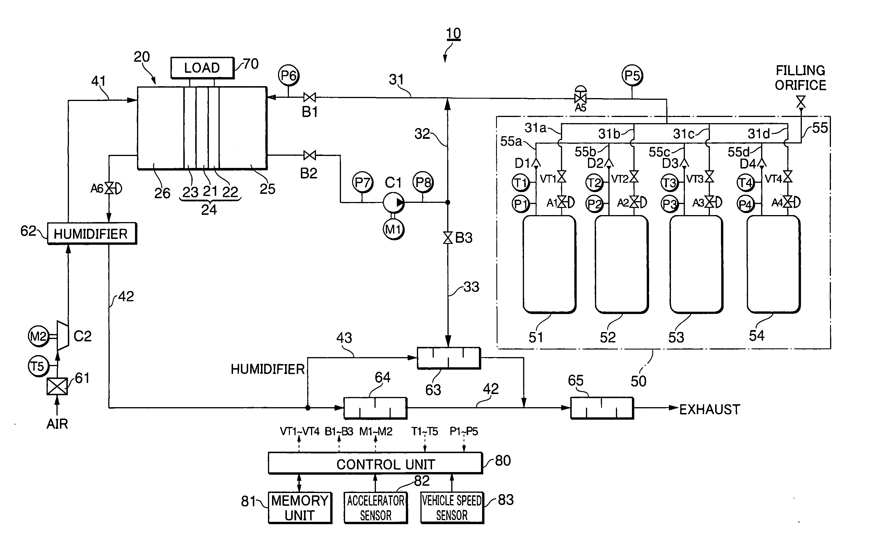
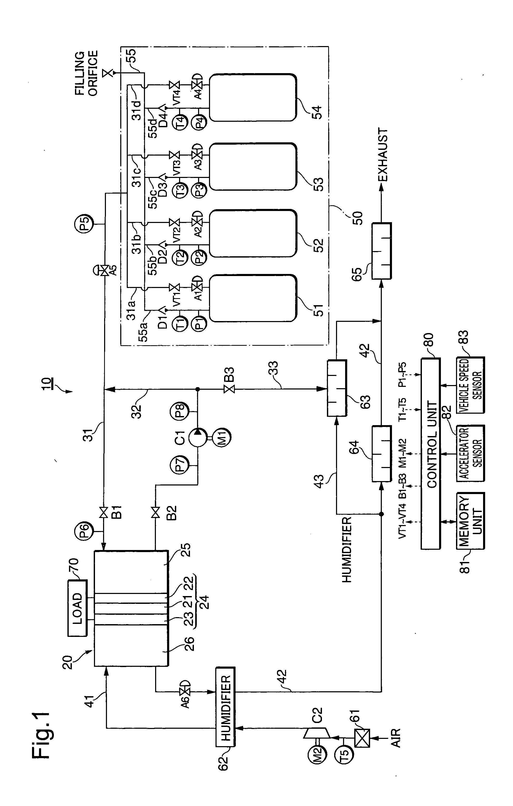
[0063]FIG. 1 is an explanatory diagram illustrating a fuel cell system 10 according to a first embodiment. In FIG. 1, the fuel cell system 10 is shown focusing on a hydrogen supply system. The fuel cell system 10 is structured as an on-board electrical generator for generating electricity, mounted on a fuel cell electric vehicle (FCEV), where a fuel cell 20 that receives a supply of reactive gases (a fuel gas and an oxidizing gas) are received and electricity is generated. The fuel cell 20 is a membrane / electrode assembly (MEA) provided with an anode 22 on one surface of a polymer electrolytic layer 21, made from, for example, an ion exchange membrane that has proton conductivity, made from a fluorinated resin, and a cathode 23 formed by, for example, screen printing, on the other surface thereof. Both sides of the membrane / electrode assembly 24 are interposed between ribbed separators (not shown), where channe...

second embodiment

B. SECOND EMBODIMENT

[0082] B-(1). System Configuration:

[0083]FIG. 7 is an explanatory diagram showing a schematic configuration of a vehicle 310 according to a second embodiment. The vehicle 310 is driven by the driving force of a motor 330, using as a source of electrical power a fuel cell 320 that is installed in a fuel cell compartment 312 in the rear of the vehicle 310. The motor 330 may use any of a variety of types, but in the present embodiment a synchronous electric motor is used. The direct current outputted from the fuel cell 320 is converted into a three-phase alternating current by an inverter 331. The motor 330 is driven by this 3-phase alternating current. The motive force of the motor 330 is transmitted to a wheel 333 through a rotating shaft 332 to drive the vehicle 310.

[0084] The fuel cell 320 produces electricity through an electrochemical reaction between hydrogen and oxygen. While any of a variety of types of fuel cells may be used in the fuel cell 320, in the ...


PUM

PropertyMeasurementUnit
pressureaaaaaaaaaa
pressureaaaaaaaaaa
temperatureaaaaaaaaaa

Abstract

A gas supply apparatus including: a tank unit that includes a tank storing a gas and a discharge mechanism discharging the stored gas to the outside of the tank at a reduced pressure of the stored gas; a temperature detector that detects a temperature of the tank; and a supply regulator that regulates supply of the gas from the tank according to the detected tank temperature.

Description

BACKGROUND [0001] 1. Technical Field [0002] The present invention relates to gas supply devices for providing to the outside gas stored in a tank. [0003] 2. Related Art [0004] Devices for supply hydrogen gas to fuel cell, which use hydrogen gas as fuel, have been known as gas supply devices that supply to the outside gas that is stored in a tank. [0005] JP-A-2001-295996 and JP-A-8-115731 disclose gas supply devices that supply hydrogen gas that is stored in a plurality of tanks using a hydrogen-occluding alloy. [0006] JP-A-2002-181295 discloses a gas supply device that supplies hydrogen from within a tank for storing high-pressure hydrogen. [0007] When a gas stored in a tank is supplied, the temperatures of the tank-related components such as the tank main unit, regulators, valves and the like fall due to the adiabatic expansion of the gas supplied from the tank. There is a problem in that excessive reductions in temperature of the tank-related parts from the room temperatures of th...

Claims


Application Information

Patent Timeline
Patent Type & Authority Applications(United States)
IPC IPC(8): H01M8/04B67D5/08B67D7/08F17C5/00F17C5/06F17C7/00F17C11/00F17C13/02
CPCF17C5/007Y02E60/50F17C7/00F17C11/005F17C13/026F17C2221/012F17C2223/0123F17C2223/036F17C2225/0123F17C2225/036F17C2227/043F17C2250/032F17C2250/0439F17C2270/0139F17C2270/0176H01M8/04089H01M8/04208Y02E60/321F17C5/06Y10T137/0318Y10T137/2567Y02E60/32F17C11/00
Inventor MIKI, YOSHIYUKISHIRAI, KAZUNARIKIMURA, ATSUFUMIYOSHIDA, NAOHIROYUMITA, OSAMU
Owner TOYOTA JIDOSHA KK
Why Eureka
Try Eureka