
Carbon monoxide removing method, carbon monoxide removing apparatus, method for producing same, hydrogen generating apparatus using same, and fuel cell system using same

a carbon monoxide and removing method technology, applied in the direction of physical/chemical process catalysts, sustainable manufacturing/processing, separation processes, etc., can solve the problems of deteriorating the capability of the reaction vessel to eliminate carbon monoxide per unit volume, deteriorating the capacity of the reaction vessel, and increasing the size of the hydrogen generating apparatus and the fuel cell system

Inactive Publication Date: 2006-09-21
KK TOSHIBA
View PDF9 Cites 10 Cited by
  • Summary
  • Abstract
  • Description
  • Claims
  • Application Information

AI Technical Summary

Benefits of technology

The patent describes a CO removing apparatus and method that can remove carbon monoxide from a gas containing carbon monoxide, carbon dioxide, and hydrogen. The apparatus includes a CO removing portion that removes at least a part of carbon monoxide by accelerating the methanation reaction, a catalyst portion in the CO removing portion that contains ruthenium supported by alumina, and a heating portion that heats the catalyst portion to a temperature of 250°C or more. The apparatus can be used in fuel cell systems to generate electricity from hydrogen. The technical effect of the invention is to provide a more efficient and effective method for removing carbon monoxide from gas mixtures.

Problems solved by technology

Carbon monoxide deteriorates the anode catalyst of the fuel cell stack to cause the deterioration of electricity generating properties.
However, in order to reduce the concentration of carbon monoxide by oxidizing carbon monoxide contained in the reformed gas, it is necessary that a unit for supplying oxygen into the reformed gas, e.g., air pump be separately provided, causing the rise of the size of the hydrogen generating apparatus and the fuel cell system to disadvantage.
Accordingly, the capability of the reaction vessel of eliminating carbon monoxide per unit volume is deteriorated.
As a result, a larger reaction vessel is needed, causing the rise of the size of the hydrogen generating apparatus and the fuel cell system.

Method used


Image

  • Carbon monoxide removing method, carbon monoxide removing apparatus, method for producing same, hydrogen generating apparatus using same, and fuel cell system using same
  • Carbon monoxide removing method, carbon monoxide removing apparatus, method for producing same, hydrogen generating apparatus using same, and fuel cell system using same
  • Carbon monoxide removing method, carbon monoxide removing apparatus, method for producing same, hydrogen generating apparatus using same, and fuel cell system using same

Examples


first embodiment

(First Embodiment)

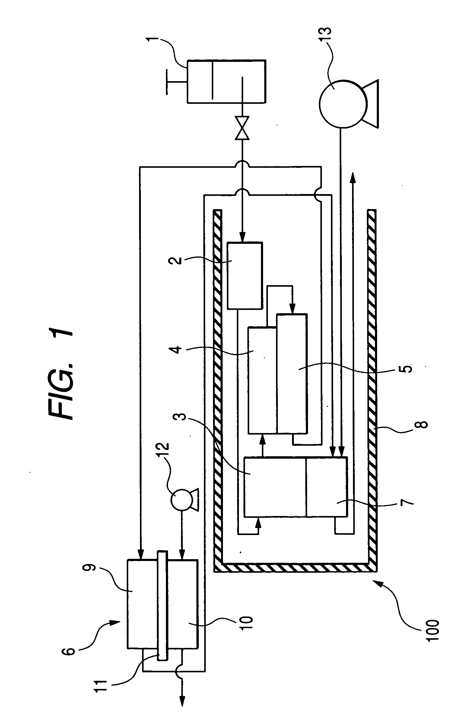
[0027]FIG. 1 illustrates a first exemplary embodiment of a CO removing apparatus according to the invention and a fuel cell system using the same.

[0028] The fuel cell system includes a hydrogen generating apparatus 100 and a fuel cell 6.

[0029] The hydrogen generating apparatus 100 includes a fuel supplying unit 1. The fuel supplying unit 1 has a mixture of an organic compound containing carbon and hydrogen as a fuel for the fuel cell system and water stored therein. As a fuel there may be used a mixture of dimethyl ether and water or a mixture of dimethyl ether, water and an alcohol. As such an alcohol there is preferably used methanol, ethanol or the like. In particular, methanol is preferably used because the mutual solubility of dimethyl ether and water can be enhanced.

[0030] As the fuel supplying unit 1 there may be used, e.g., a pressure vessel attached detachably to the fuel cell system. The fuel can be supplied into the vaporization portion 2 described la...

second embodiment

(Second Embodiment)

[0068]FIG. 6 depicts a second embodiment of the hydrogen generating apparatus and fuel cell system according to the invention. Where the parts are the same as those of the first embodiment shown in FIG. 1, the same reference numerals are used. These parts will not be described.

[0069]FIG. 6 depicts a perspective view of the interior of the CO removing portion 5b. The other configurations are the same as those of the first embodiment. The CO removing portion 5b comprises a heater 41 (heating portion) provided therein in addition to the combustion portion 7. The heater 41 may be a cartridge heater having a high resistivity metal wound on an insulating material. The heater 41 receives an external energy, e.g., electric power, if the heater 41 is a cartridge heater. The electric power to be supplied into the heater 41 is supplied, e.g., from the fuel cell 6. When externally supplied with an energy, the heater 41 generates heat to heat the CO removing portion 5.

[0070]...

third embodiment

(Third Embodiment)

[0079]FIG. 7 depicts a third embodiment of the hydrogen generating apparatus and fuel cell system according to the invention. Where the parts are the same as those of the first embodiment shown in FIG. 1, the same reference numerals are used. These parts will not be described.

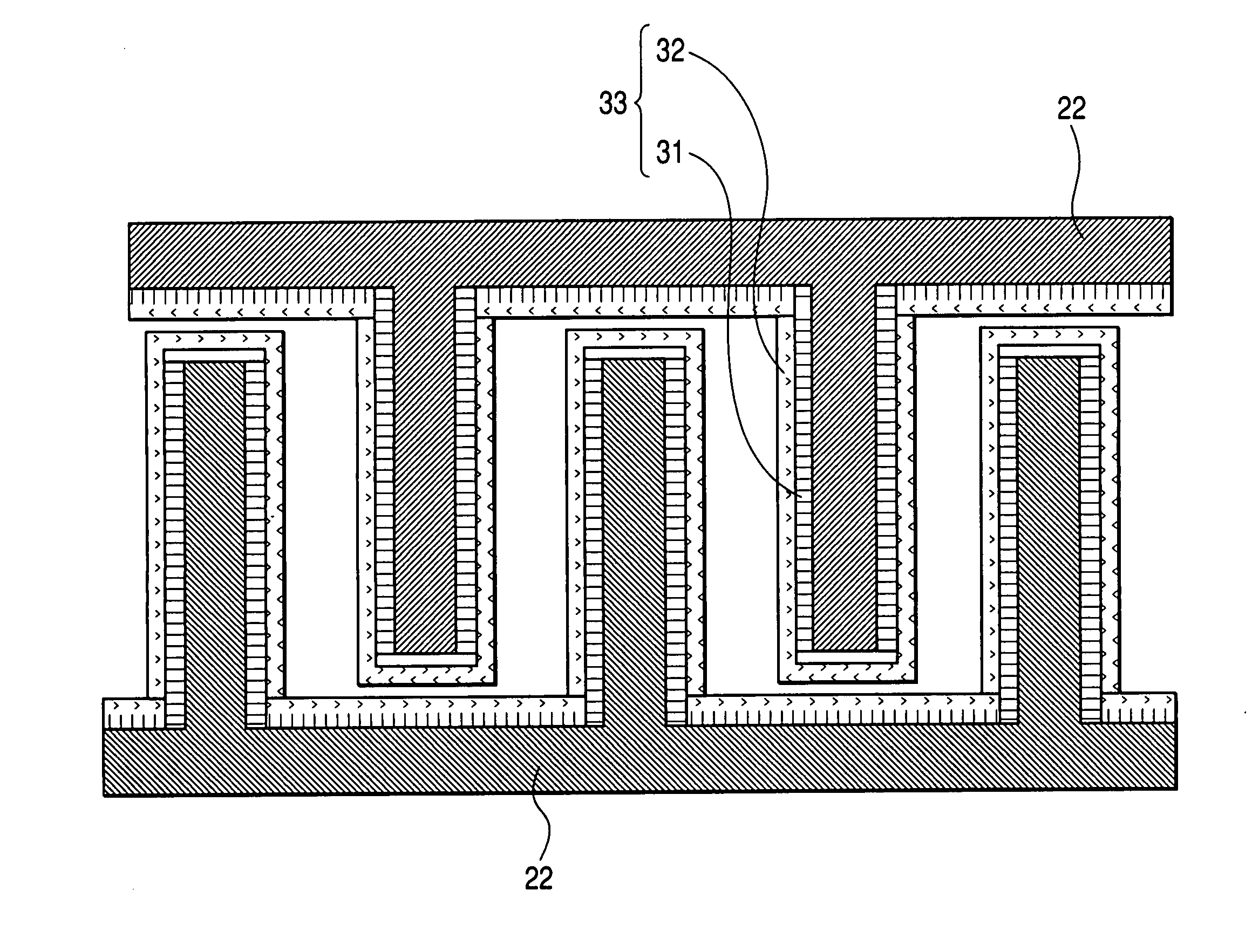
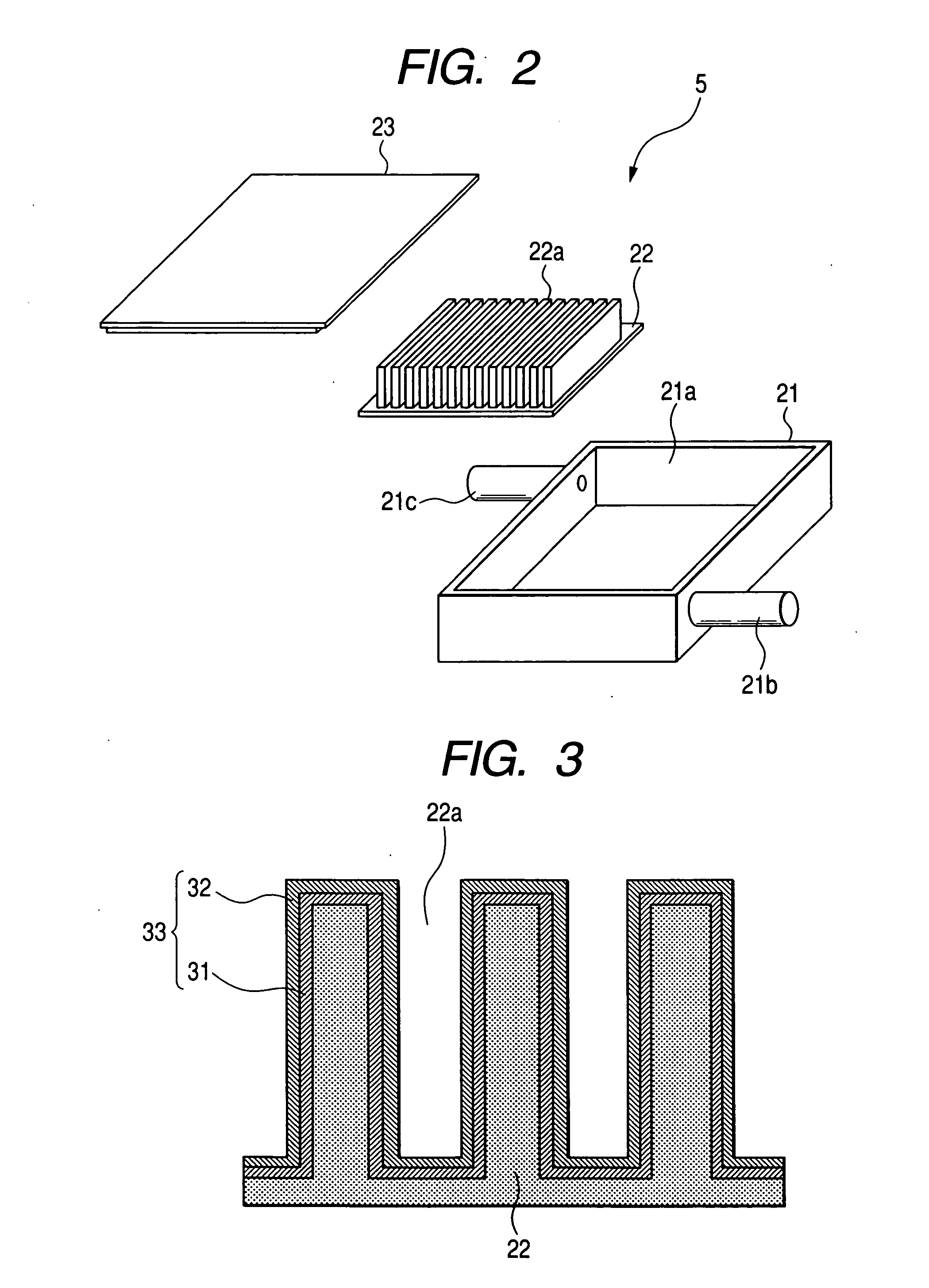
[0080]FIG. 7 depicts an exploded perspective view of the CO removing portion 5. The CO removing portion 5 comprises a catalyst portion 24 provided therein in place of the catalyst portion 22 according to the first embodiment. The catalyst portion 24 has a catalyst layer 33 provided on the surface of aluminum or alloy containing aluminum having a large number of voids or on the surface of the voids of aluminum or aluminum alloy. The pore of the void preferably is 1 mm or less. As aluminum or aluminum-containing alloy there may be used a porous aluminum material, a aluminum foam or a honeycomb-like aluminum material. The catalyst layer 33 is the same as that of the first embodiment and thus wil...


PUM

PropertyMeasurementUnit
temperatureaaaaaaaaaa
widthaaaaaaaaaa
pore diameteraaaaaaaaaa

Abstract

A hydrogen generating apparatus and a fuel cell system, which can be reduced in size, are provided. The hydrogen generating apparatus and the fuel cell system each has a CO removing portion. A catalyst portion formed by aluminum is provided on the surface of a CO removing portion for accelerating the methanation reaction of a part of carbon monoxide contained in a reformed gas. The catalyst portion includes a catalyst layer having ruthenium supported on γ-alumina formed by the anodization of the surface thereof. Heating is effected such that the temperature of the catalyst portion reaches 250° C. or more.

Description

[0001] The present application claims foreign priority based on Japanese Patent Application No. JP2005-77077 filed on Mar. 17, of 2005, the contents of which is incorporated herein by reference. FIELD OF THE INVENTION [0002] The present invention relates to a CO (carbon monoxide) removing method and a CO removing apparatus, and more particularly to a CO removing method and apparatus which can be reduced in size, a method for the production of the CO removing apparatus, a hydrogen generating apparatus using the same and a fuel cell system using the same. BACKGROUND OF THE INVENTION [0003] In recent years, there has been developed a fuel cell system comprising in combination a reformer for reforming a light hydrocarbon such as natural gas and naphtha or an alcohol such as methanol in the presence of a reforming catalyst to produce a gas containing hydrogen and a fuel cell having a fuel electrode (anode) into which the reformed gas is supplied and an oxidant electrode (cathode) into wh...

Claims


Application Information

Patent Timeline
Patent Type & Authority Applications(United States)
IPC IPC(8): H01M8/06B01J19/00B21D51/16
CPCB01J19/0093Y10T29/49345B01J35/1061B01J37/0203B01J37/0219B01J2219/00783B01J2219/00822B01J2219/00824B01J2219/00835B01J2219/0086B01J2219/00873C01B3/586C01B2203/0227C01B2203/0283C01B2203/0445C01B2203/047C01B2203/066C01B2203/0822C01B2203/0827C01B2203/1288H01M8/04022H01M8/0612H01M8/0668Y02E60/50B01J23/462Y02P20/10B01J35/647
Inventor ISOZAKI, YOSHIYUKITEZUKA, FUMINOBUHANAKATA, YOSHIOKITAMURA, HIDEOSATO, YUUSUKE
Owner KK TOSHIBA
Learn More