
Etching solution, method of etching and printed wiring board

a technology of etching solution and printed wiring board, which is applied in the direction of cable/conductor manufacturing, chemistry apparatus and processes, and metal adhesion improvement of insulation substrates, etc., can solve the problems of difficult to achieve a high density of wiring, difficult to make etching in any intended direction, and inability to yield inexpensive printed wiring boards

Active Publication Date: 2006-09-07
IBIDEN CO LTD
View PDF0 Cites 34 Cited by
  • Summary
  • Abstract
  • Description
  • Claims
  • Application Information

AI Technical Summary

Benefits of technology

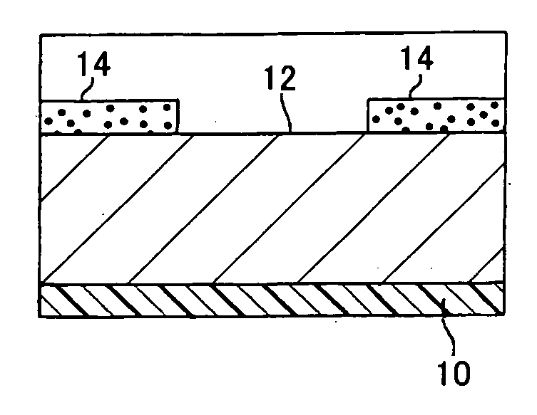
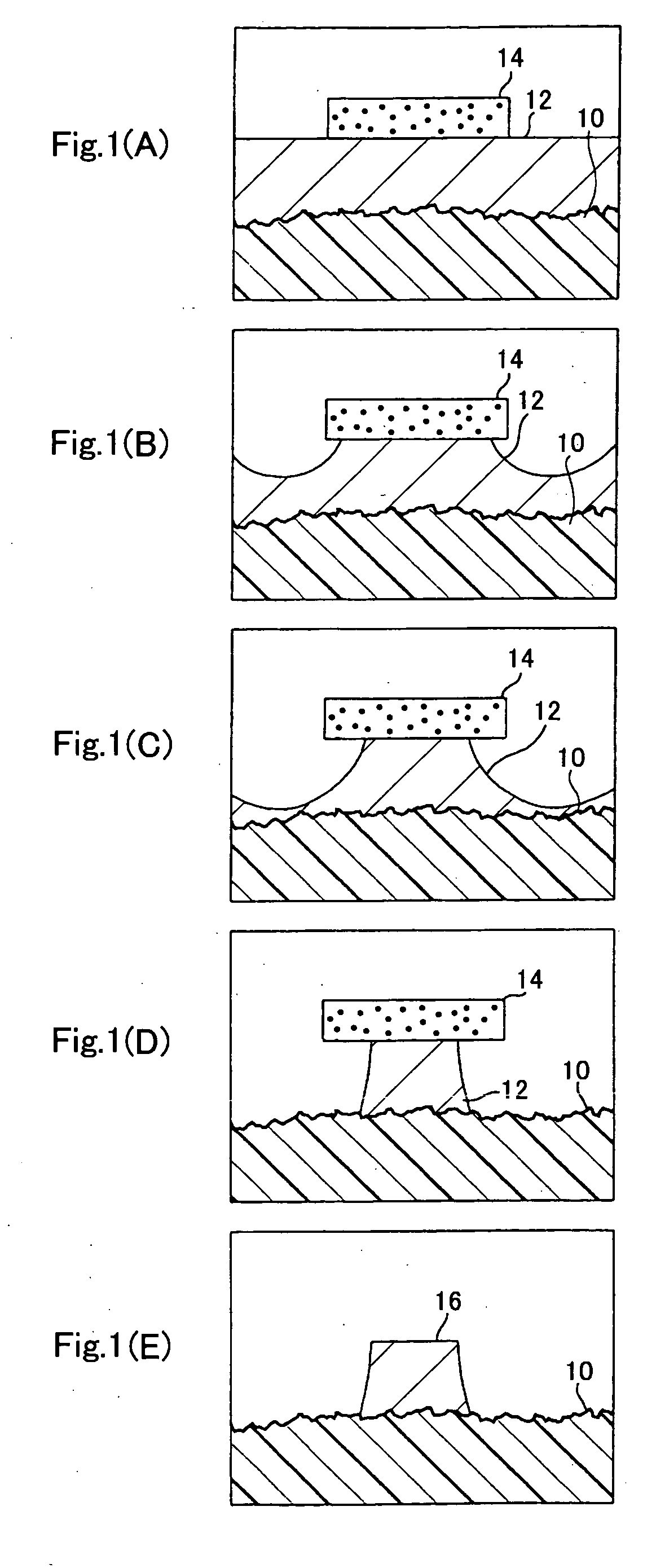
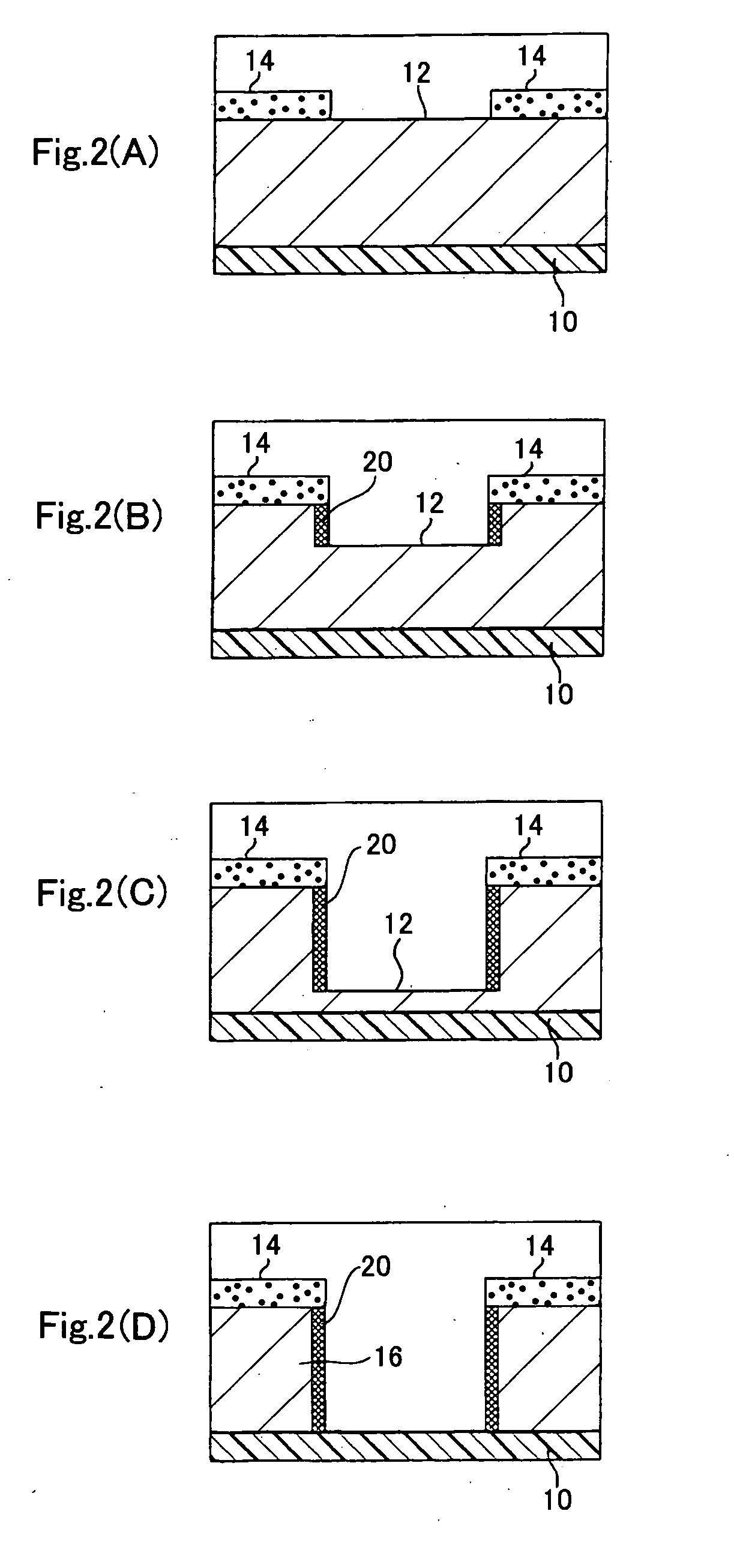
[0016] According to the present invention, a triazole type compound capable of effectively forming a coating that effectively inhibits etching is added in a high concentration to a conventional cupric-chloride etching solution based on cupric chloride, and a copper layer or foil (will be referred to simply as “copper layer” hereunder) not covered with any etching resist is etched in the direction of thickness with the etching solution in the etching step while an etching-inhibiting coating is selectively reaction-deposited on part of the copper layer laid nearly just under the edge of the etching resist, to attain a considerably improved effect of side-etching inhibition.
[0017] Thus, a fine-pitch circuit pattern whose traces are extremely fine can be formed by etching nearly as designed without adopting any additive method that can provide expensive printed wiring boards. Therefore, it is possible to form a high-density circuit pattern having the extremely fine traces, which leads to a higher wiring density of a printed wiring board.
[0032] Note that by adding the predetermined amount of surface active agent to the etching solution according to the present invention, it is possible to lower the external pressure such as a sufficient liquid flow or the like to separate the etching-inhibiting coating formed on the copper layer not covered with the etching resist. More particularly, in an etching process using the etching solution having a surface active agent added thereto, the etching-inhibiting coating can be sufficiently separated under a spray pressure of about 0.1 to 0.3 Mpa. However, in an etching process using the etching solution having no surface active agent added thereto, a higher spray pressure of about 0.3 to 0.6 MPa can be used to effectively separate the etching-inhibiting coating.
[0037] (4) Also the above object can be attained by providing a printed wiring board having a circuit pattern formed by either the etching method (2) or (3) above, wherein on the side walls of the circuit pattern, there are formed nonuniform irregularities that improve the adhesion between the circuit pattern and an insulating resin layer covering the circuit pattern. That is, by stacking printed wiring boards each having a circuit pattern having such nonuniform irregularities formed on the side walls thereof one on the other with an insulating resin layer (adhesive layer) such as a resin film, prepreg or the like being laid between the printed wiring boards, it is possible to provide a multilayer printed wiring board superior in adhesion between a conductor layer and insulating layer.

Problems solved by technology

With this etching technique, it is difficult to make etching in any intended direction, and provide inexpensive high-density wiring boards.
Since a wiring interval should be determined taking the side etching in consideration in designing a high-density wiring, it is difficult to attain a high density of wiring.
However, the conventional additive method includes complicated processes and thus cannot have yielded any inexpensive printed wiring boards as final products.
However, although the Japanese Patent Application Laid Open Nos. 2003-306784 and 2003-306784 discloses the additive that will inhibit the side etching made by the cupric chloride and ferric chloride in the etching process, a most effective one selected from among such additives attains such an inhibition about 30% higher than with the conventional etching solutions and this effect of side-etching inhibition is not sufficient for forming a high-density wiring.

Method used


Image

  • Etching solution, method of etching and printed wiring board
  • Etching solution, method of etching and printed wiring board
  • Etching solution, method of etching and printed wiring board

Examples


example 1

[0151] (1) Preparing an Etching Solution

[0152] To a cupric chloride solution (cupric chloride of 2 to 2.2 mol / L in concentration and hydrochloric acid of 2 to 3 mol / L in concentration), BTA (benzotriazole) as a BTA compound was added in 800 ppm, and then alkyldimethyl betaine aminoacetate as amphoteric surface active agent and polyoxyethylene alkyl ether as anionic surface active agent was added in 5000 ppm in total to the mixture, to thereby prepare an etching solution.

[0153] To prepare the above etching solution, first BTA (benzotriazole) as BTA compound was added to a mixed aqueous solution of amphoteric and anionic surface active agents and then the mixture was agitated until BTA was completely solved in the aqueous solution containing the surface active agents, thereby preparing an additive. This additive was added to the cupric chloride solution to prepare the etching solution.

[0154] (2) Forming an Etching Resist Layer

[0155] A 70 μm-thick copper foil to form a copper wirin...

example 2

[0166] A printed wiring board was produced similarly to the example 1 except that an etching solution was prepared without adding any surface active agent and the spray pressure included in the etching conditions was 0.5 to 0.6 MPa.

[0167] Note that to prepare the above etching solution, the additive was prepared by adding a predetermined amount of BTA to a KOH aqueous solution of pH 13, for example, and agitating the mixture until BTA was completely solved in the KOH. This additive was added to the cupric chloride solution to prepare the etching solution.

example 3

[0168] A printed wiring board was produced similarly to the example 1 except that BTA as the BTA compound was added in 1005 ppm to the cupric chloride solution.


PUM

PropertyMeasurementUnit
depthaaaaaaaaaa
pHaaaaaaaaaa
pressureaaaaaaaaaa

Abstract

There is provided an etching solution comprised of a cupric chloride solution and a high-concentration triazole type compound added to the cupric chloride solution and capable of forming an etching-inhibiting coating. In a process of forming a circuit pattern by etching with the etching solution, an etching-inhibiting coating is selected formed on parts of a copper foil laid under the edge of an etching resist to effectively inhibit horizontal side-etching of the copper foil from the edge of the etching resist. Also, nonuniform irregularities formed on the side wall of the circuit pattern by the etching improves the adhesion between the circuit pattern and an insulating resin layer covering the circuit pattern.

Description

FIELD OF THE INVENTION [0001] The present invention generally relates to an etching solution intended for use in the process of etching a copper layer to form an electrical circuit, and more particularly to an etching solution having mixed therein an additive containing a component that will form a coating effectively inhibiting the etching, and which is thus capable of anisotropic etching (high etch factor) even in processing a metallic material such as copper, an etching method in which the etching solution is used, and to a printed wiring board having a wiring pattern formed by the etching method. BACKGROUND ART [0002] With the recent remarkable innovation of the electronics, the industries of printed wiring boards are strictly urged to provide inexpensive high-density wiring boards. However, etching in the conventional subtractive method (tinting method) permits isotropic forming of a circuit pattern. With this etching technique, it is difficult to make etching in any intended d...

Claims


Application Information

Patent Timeline
Patent Type & Authority Applications(United States)
IPC IPC(8): C23F1/00C09K13/00H01L21/302C23F1/02C23F1/18C23F1/34H01L21/3213H05K3/06H05K3/38
CPCC09K13/00C23F1/02C23F1/18C23F1/34H05K2203/124H05K3/064H05K3/067H05K3/383H05K2203/0597H01L21/32134H05K3/06
Inventor TAKAHASHI, TSUNEHISASAWA, SHIGEKIMATSUI, KAZUHIKO
Owner IBIDEN CO LTD
Learn More