
Molding compounds for use in furnace blower housings and blower housings molded from these compounds

Inactive Publication Date: 2006-08-31
PREMIX INC
View PDF9 Cites 8 Cited by
  • Summary
  • Abstract
  • Description
  • Claims
  • Application Information

AI Technical Summary

Benefits of technology

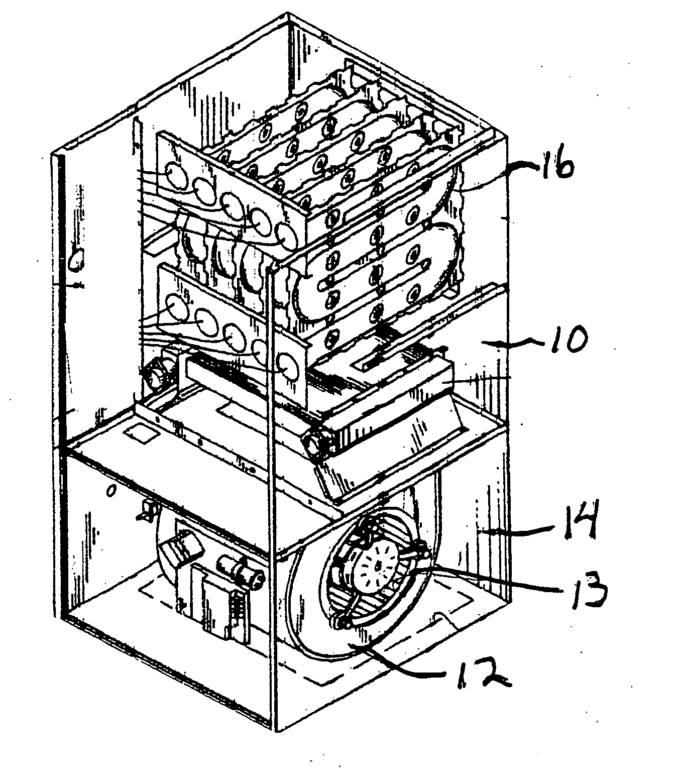
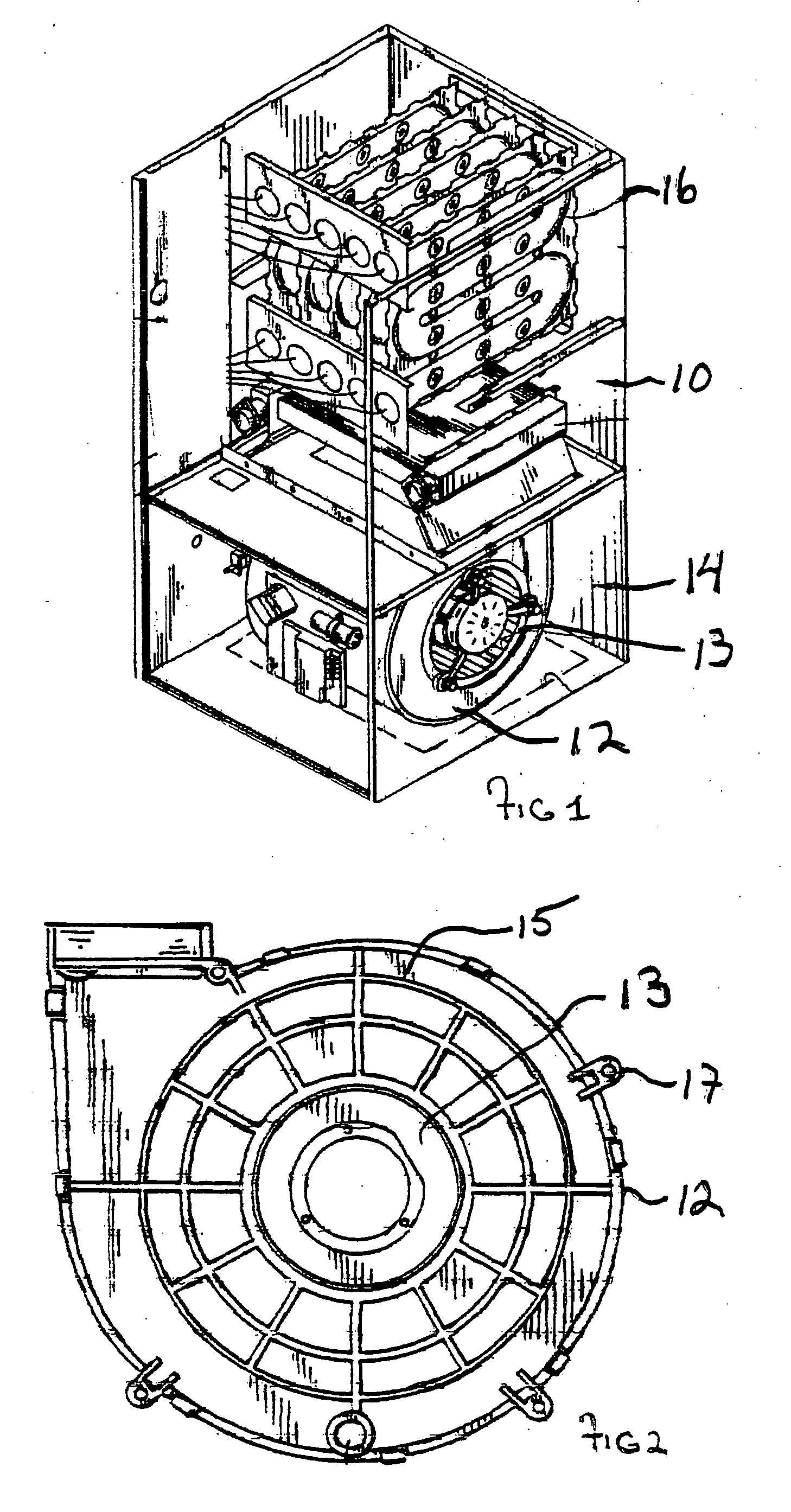
[0013] The foregoing improvements in specimens molded from these compositions enable the low cost mass production of blowers used in hot air furnaces / air handlers, and further allow for the far greater flexibility in blower housing design in order to meet the mandate of improved unit efficiency and also permit the combination of functions in a single article so as to permit greater fabrication efficiency and lower cost.

Problems solved by technology

One of the issues studied involved air flow control through the blower housing.
This leads to the possibility of injury to workers who are exposed to sharp edges, and extreme heat in welding.
The final assembly of the blower requires intensive labor and puts the assembly worker at risk of injury through cuts or burns.
This adds considerable expense to the fabrication of the housing.
In addition to the stress of elevated temperatures, the environment can be corrosive, and as some furnaces are located outside residences, they can also be subjected to cold temperatures.
These applications often involve the use of very expensive compositions, which can be used since the size is small.
However, despite the use of molded polymerics for these other applications and for housings in window air conditioners for well over 30 years, the HVAC industry has failed to capitalize on the many advantages which could be realized through the use of molded polymeric blower housings for hot air furnaces.
An additional problem is the lack of understanding in the compounding industry of how to achieve sufficient structural reinforcement, such as through the use of glass fiber reinforcement, while maintaining proper sound dampening properties for this application.

Method used


Image

  • Molding compounds for use in furnace blower housings and blower housings molded from these compounds
  • Molding compounds for use in furnace blower housings and blower housings molded from these compounds
  • Molding compounds for use in furnace blower housings and blower housings molded from these compounds

Examples


examples

[0042] Resin A is 31610 styrene solution of an unsaturated polyester resin based on propylene glycol and isophthalic acid and maleic anhydride sold by Reichhold.

[0043] Monomer A is styrene.

[0044] R-100 is a polystyrene solution which acts as a low shrink additive?

These ingredients are added together to comprise the base resin for 100 phr.

[0045] Flame retardant A is FR-121-(DBDPO).

[0046] Synergist A is Antimony Trioxide.

[0047] Flow modifier A is FN-510, a linear low-density polyethylene from Equistar Chemicals, L.P. of Houston, Tex.

[0048] Initiator A is Trigonox. C, an alkylperoxyester (t-butylperbenzoate) available from Durr Marketing in Pittsburgh, Pa.

[0049] Initiator B is Trigonox 210P50 an alkylperoxyester (tert-Butyl peroxy-2-ethylhexanoate available from Durr Marketing in Pittsburgh, Pa.

[0050] Initiator C is Trigonox BPIC-C75 Tert-butyl peroxy isopropyl carbonate from Durr Marketing in Pittsburgh, Pa.

[0051] Inhibitor A is IN-9073 is Toluhydroquinone in Diethylene Glyc...


PUM

PropertyMeasurementUnit
Fractionaaaaaaaaaa
Fractionaaaaaaaaaa
Percent by massaaaaaaaaaa

Abstract

The invention provides blower housings for air handlers and hot air furnaces which are made from molding compounds that allow for wide flexibility in molding complex configurations so as to improve blower efficiency, which improve manufacturing efficiency and safety and provide suitable mechanical properties, safety in use, and sound dampening. These compounds are generally liquid thermosetting molding resins which comprise a thermoset resin matrix such as a isophthalate polyester having a specific loading of glass reinforcing fibers. The compositions also include flame retardant additives. They are further formulated to meet the desired molding characteristics; to withstand the operating temperatures to which they will be exposed; and to have a predetermined strength and a desirable user interface including appearance, and odor. Typically, the compounds will have a glass transition temperature from about 160° C. (320° F.) to about 185° C. (365° F.).

Description

[0001] This application is based on U.S. Provisional Application Ser. No. 60 / 656,582, filed on Apr. 27, 2004 FIELD OF INVENTION [0002] The field of invention is molding compounds that are particularly suitable to be molded into a blower housing for use in hot air handlers, hot air furnaces and other HVAC applications. These compounds are generally liquid thermosetting molding resins typically characterized as bulk molding compositions (“BMC”), sheet molding compositions (“SMC”), and / or thick molding compositions (“TMC”). They can be used in molding processes such as compression, transfer, injection / compression molding and injection molding. [0003] Products molded from the composition of this invention desirably have adequate glass transition temperatures, flame retardance, and desirable surface characteristics; high and low temperature stability, corrosion and shrink resistance; low odor, sound damping strength; and cost. Desirably the compositions include a thermoset resin matrix s...

Claims


Application Information

Patent Timeline
IPC IPC(8): F04D29/44
CPCF04D29/023F04D29/4206F05D2300/44F05D2300/603F04D29/4226
Inventor BUTLER, KURT I.SEARL, STEVEN T.
Owner PREMIX INC
Learn More