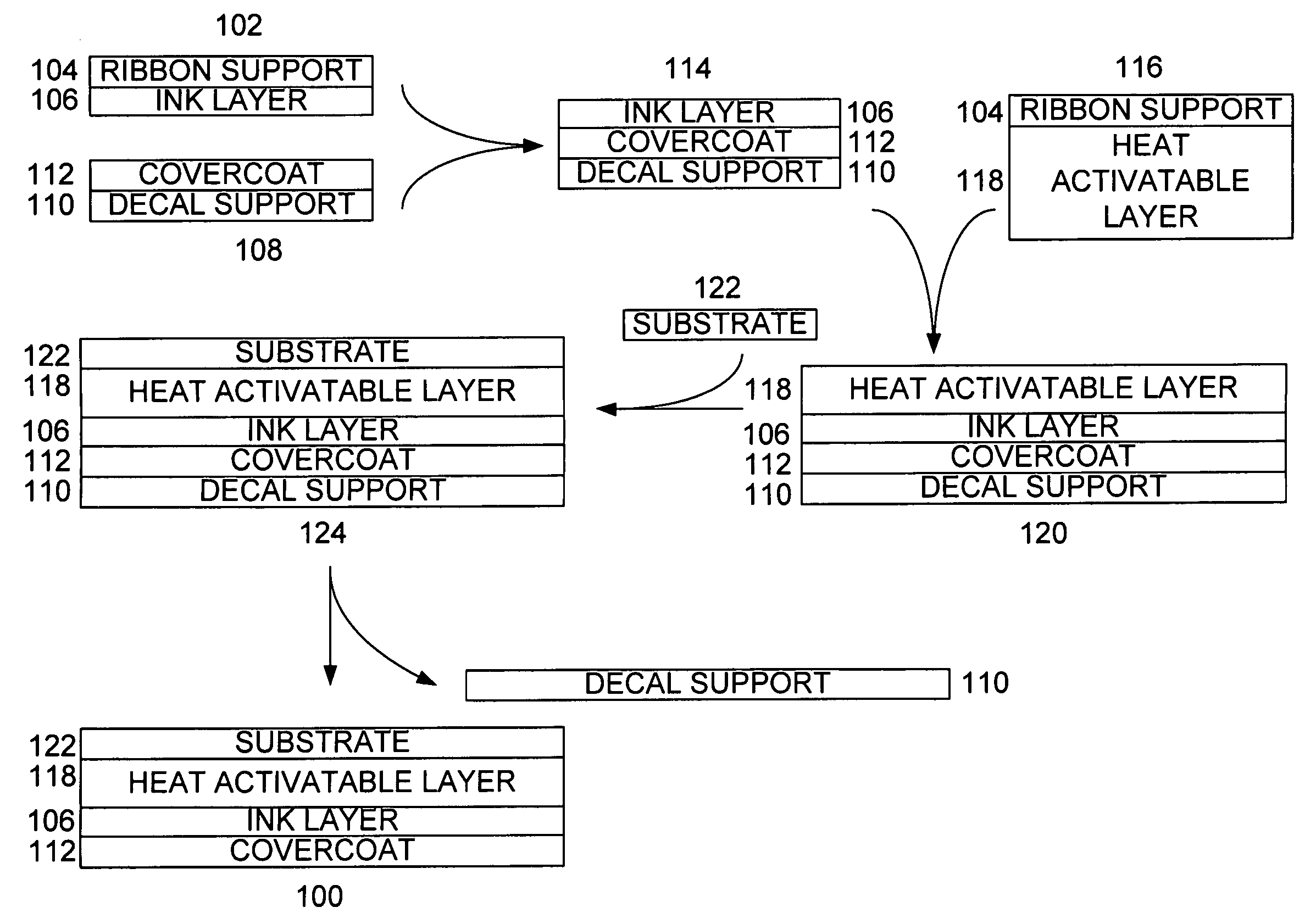
Digital decoration and marking of glass and ceramic substrates
a technology of ceramic substrates and digital decoration, applied in the field of ceramic decals, can solve the problems of prior art failing to provide a digital decal, difficult and costly alteration of images for fabricators, and inherently limited types of images that can be transferred by silver screen
- Summary
- Abstract
- Description
- Claims
- Application Information
AI Technical Summary
Problems solved by technology
Method used
Image
Examples
examples
[0083] The follow examples illustrate some preferred aspects of applicants' decals. The following Examples are presented to illustrate a portion of the claimed inventions but are not to be deemed limitative thereof. Unless otherwise specified, all parts are by weight, and all temperatures are in degrees Celsius.
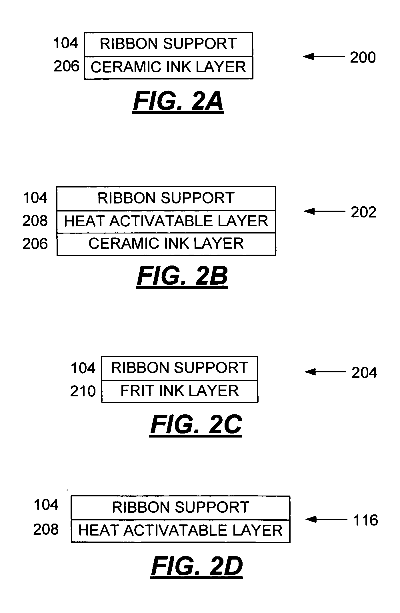
[0084] The examples below describe a variety of ceramic inks, overprints and heat activatable layers as a part of the imaged covercoat to improve adhesive transfer to the glass and ceramic substrates. They describe, in part, materials and / or reagents that are also described in U.S. patent application Ser. No. 10 / 621,976, the contents of which is hereby incorporated by reference into this specification.
example # 1
Example #1
[0085] In this example a covercoated transfer sheet was prepared with a flexible substrate. The flexible substrate was a 90 gram per square meter basis paper made from bleached softwood and hardwood fibers. The surface was sized with starch. The face side of the base paper was then resin coated with a 20 gram per square meter thick layer of polyethylene using an extrusion coating process. A covercoat coating composition was prepared for application to the face coat of the flexible paper substrate. The cover coat was prepared by coating Joncryl 617 (a styrene / acrylic emulsion sold by Johnson Polymers, Racine, Wis.) at a dry coat weight of 15 grams per square meter using a Meyer rod. The coated paper was then allowed to dry at ambient temperature for 16 hours.
[0086] In this example a thermal transfer ribbon was prepared for printing onto covercoated transfer paper. The ceramic ink to be coated on the thermal transfer ribbon was prepared by mixing 18.27 grams of hot toluene ...
example # 2
Example #2
[0091] The process used in Example 1 was followed except the ceramic ink for this example was prepared by mixing 16.61 grams of hot toluene with 5.99 grams of methacrylate polymer Dianal BR113 (Dianal America, Pasadena, Tex.), 1.47 grams of ethylene vinyl acetate Elvax 250 (Dupont, Wilmington, Del.), and 0.45 grams of polyamide gellant, Uniclear 100 (Arizona Chemical). These components were allowed to dissolve completely and then cooled to ambient temperature. Subsequently, 3.14 gram of dioctylphthalate (Chemcentral, 3709 River Road Town of Tonawanda, N.Y.), 32.32 grams of flux 20-8380 (Ferro Corp, Washington, Pa.), 6.02 grams of Zirocn Opacifier Superpax Plus (Cookson-Matthey, Jacksonville, Fla.), 5.43 grams of 94C1001 Flux (Johnson & Matthey, 498 Acorn Lane, Dowington, Pa.) and 0.99 grams of Cerdec Black oxide 1795 (Cerdec / Ferro, Washington, Pa.) were added to the mixture. To the mixture was added 50 grams of ceramic milling media (0.3 mm). The mixture was milled on a Re...
PUM
| Property | Measurement | Unit |
|---|---|---|
| temperature | aaaaa | aaaaa |
| temperature | aaaaa | aaaaa |
| pressure | aaaaa | aaaaa |
Abstract
Description
Claims
Application Information
 - R&D
- Intellectual Property
- Life Sciences
- Materials
- Tech Scout
- Unparalleled Data Quality
- Higher Quality Content
- 60% Fewer Hallucinations
Browse by: Latest US Patents, China's latest patents, Technical Efficacy Thesaurus, Application Domain, Technology Topic, Popular Technical Reports.
© 2025 PatSnap. All rights reserved.Legal|Privacy policy|Modern Slavery Act Transparency Statement|Sitemap|About US| Contact US: help@patsnap.com


