
Apparatus for processing materials in supercritical fluids and methods thereof

a technology of supercritical fluids and apparatuses, applied in the direction of supercritical condition processes, separation processes, instruments, etc., can solve the problems of limited processing limitations of conventional steel hot-wall pressure vessels (e.g., autoclaves), insufficient hot-wall pressure vessels for some processes, and insufficient cold-wall pressure vessels

Active Publication Date: 2006-08-10
SLT TECH
View PDF73 Cites 164 Cited by
  • Summary
  • Abstract
  • Description
  • Claims
  • Application Information

AI Technical Summary

Benefits of technology

The patent describes an apparatus and method for growing crystals using a supercritical fluid and a pressurized gas. The apparatus includes a capsule for containing the supercritical fluid and a pressure vessel for containing the pressurized gas. A pressure control device is used to balance the pressure within the capsule with the surrounding pressure of the gas in the pressure vessel based on sensed environmental conditions. The technical effect of this invention is to provide a more stable and controlled environment for crystal growth, resulting in higher quality crystals.

Problems solved by technology

The processing limitations for conventional steel hot-wall pressure vessels (e.g., autoclaves) are typically limited to a maximum temperature of about 400 Degrees Celsius and a maximum pressure of 0.2 GigaPascals (GPa).
Therefore, these hot-wall pressure vessels are inadequate for some processes, such as the growth of gallium nitride crystals in supercritical ammonia, which require pressures and temperatures that extend significantly above this range in order to achieve growth rates above about 2-3 microns per hour.
In addition, existing cold-wall pressure vessels, e.g., hot isostatic presses (HIPs), may not adequately account for pressure differences between the interior of the capsule and the high pressure apparatus surrounding the exterior of the capsule.
Moreover, existing baffle plates within the capsule or pressure vessel have random holes, which do not adequately distribute the heat and substances circulating within the capsule.

Method used


Image

  • Apparatus for processing materials in supercritical fluids and methods thereof
  • Apparatus for processing materials in supercritical fluids and methods thereof
  • Apparatus for processing materials in supercritical fluids and methods thereof

Examples


Embodiment Construction

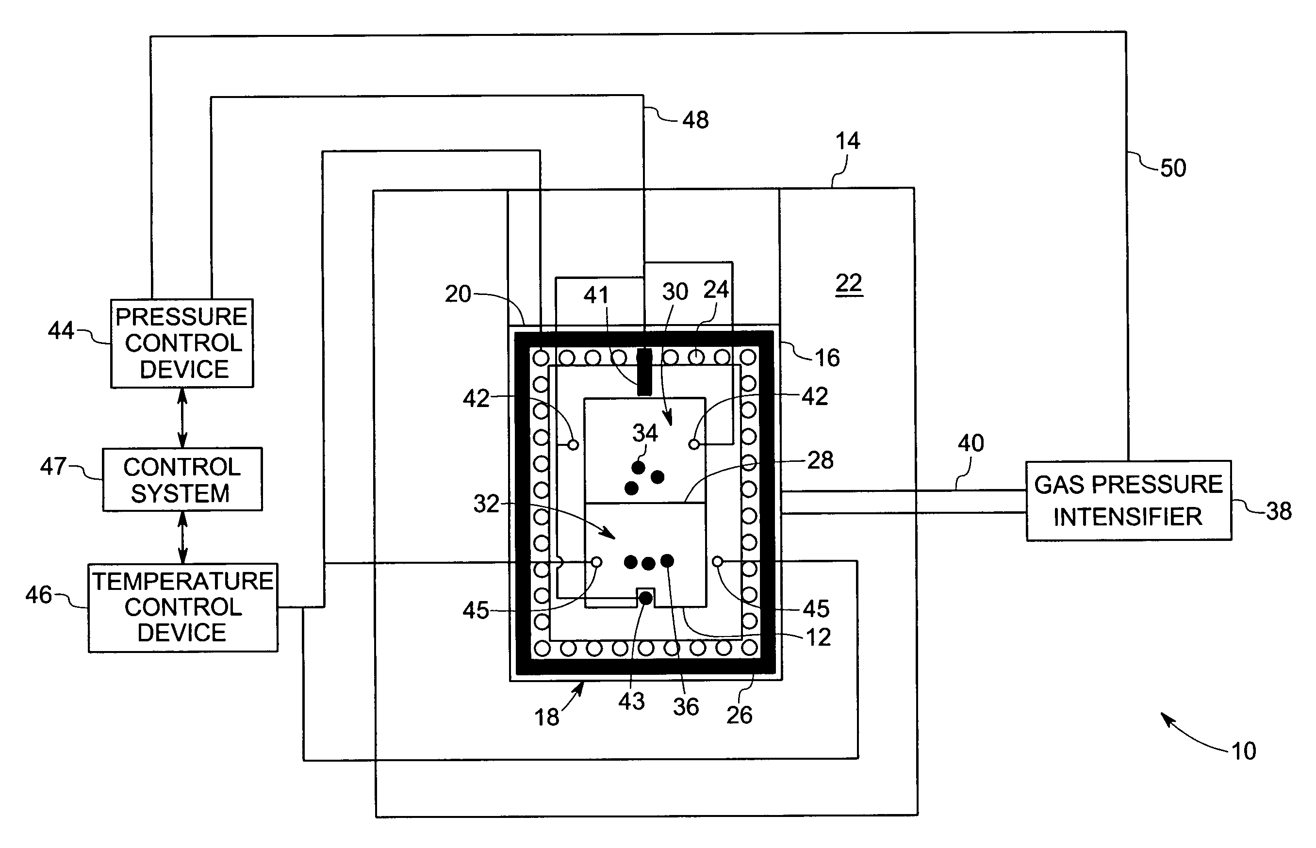
[0023] Turning now to the drawings, FIG. 1 illustrates a diagrammatical side view of a system 10 having a container or capsule 12 disposed in an apparatus 14 in accordance with certain embodiments of the present technique. The capsule 12 is chemically inert and impermeable to one material, solvent, and the supercritical fluid formed by the solvent. The capsule 12 is formed from a deformable material to allow expansion of the capsule 12 as pressure increases within the capsule 12. This prevents the capsule 12 from bursting. In one embodiment, the deformable material may comprise at least one of copper, copper-based alloy, gold, silver, palladium, platinum, iridium, ruthenium, rhodium, osmium, titanium, vanadium, chromium, iron, iron- based alloy, nickel, nickel-based alloy, zirconium, niobium, molybdenum, tantalum, tungsten, rhenium, combinations thereof, and the like. In another embodiment, the capsule 12 is formed from a cold-weldable material, such as, but not limited to, at least...


PUM

PropertyMeasurementUnit
temperatureaaaaaaaaaa
temperaturesaaaaaaaaaa

Abstract

An apparatus and method for processing materials in supercritical fluids is disclosed. The apparatus includes a capsule configured to contain a supercritical fluid, a high strength enclosure disposed about the capsule and a sensor configured to sense pressure difference between an interior and an exterior of the capsule. The apparatus also includes a pressure control device configured to adjust pressure difference of the capsule in response to the pressure difference sensed by the sensor. The apparatus further includes at least one dividing structure disposed within the capsule that divides the capsule into a seed growing chamber and a nutrient chamber.

Description

BACKGROUND [0001] The invention relates generally to techniques for processing materials in supercritical fluids. Specifically, embodiments of the invention include techniques for controlling parameters associated with a material processing capsule disposed within a high-pressure apparatus / enclosure. [0002] Supercritical fluids may be used to process a wide variety of materials. A supercritical fluid is defined as a substance beyond its critical point, i.e., critical temperature and critical pressure. A critical point represents the highest temperature and pressure at which the substance can exist as a vapor and liquid in equilibrium. In certain supercritical fluid applications, the materials being processed are placed inside a pressure vessel or other high pressure apparatus. In some cases it is desirable to first place the materials inside a container, liner, or capsule, which in turn is placed inside the high pressure apparatus. In operation, the high pressure apparatus provides ...

Claims


Application Information

Patent Timeline
Patent Type & Authority Applications(United States)
IPC IPC(8): B01D9/00
CPCB01J3/002B01J3/008B01J3/03B01J3/046B01J3/06B01J2203/0665Y10T117/1024B01J2219/00135B01J2219/00155B01J2219/00162Y10T117/1092Y10T117/10B01J2203/068Y02P20/54
Inventor D'EVELYN, MARK PHILIPGIDDINGS, ROBERT ARTHURSHARIFI, FREDDEY, SUBHRAJITHONG, HUICONGKAPP, JOSEPH ALEXANDERKHARE, ASHOK KUMAR
Owner SLT TECH
Learn More