
Exposure apparatus, exposure method and device manufacturing method

Active Publication Date: 2006-06-29
NIKON CORP
View PDF24 Cites 41 Cited by
  • Summary
  • Abstract
  • Description
  • Claims
  • Application Information

AI Technical Summary

Benefits of technology

[0009] The present invention has been made in consideration of such situations, and its objective is to provide an exposure method, an exposure apparatus, and a device manufacturing method in which the exposure accuracy when a substrate is exposed by irradiating the substrate with an exposure light via a projection optical system and a liquid can be maintained.
[0012] According to the present invention, by not performing the recovery of the liquid by the liquid recovery mechanism when the exposure light is being irradiated on the image plane side of the projection optical system, sound and / or variation due to the liquid recovery operation can be prevented from occurring during the exposure operation to the substrate, in which the exposure light is irradiated on the image plane side. Thus, the disadvantage that the exposure accuracy lowers due to the sound and / or vibration can be precluded. As for an operation in which the exposure light is irradiated on the image plane side of the projection optical system, there is, for example, other than the exposure operation to the substrate, the exposure light detection operation via the liquid by means of various light receiving sensors placed on the image lane side of the projection optical system. By not performing the liquid recovery operation by the liquid recovery mechanism also during this exposure light detection operation of the light receiving sensors, the disadvantage that the detection accuracy lowers due to sound and / or vibration can be prevented.
[0014] According to the present invention, by, after completion of the exposure to the substrate, relatively moving the stile holding member and the recovery port of the liquid recovery mechanism, the liquid that has not been recovered by the liquid recovery mechanism during the expose and remained on the substrate or the substrate holding member can be recovered. Thus, the occurrence of the disadvantages, such as the occurrence of a water mark, rusting of the apparatus, and the variation of the ambience that are due to the liquid remained, can be prevented.
[0016] In the case of a configuration in which a liquid recovery mechanism recovers a liquid on a substrate by sucking the liquid from above the substrate may arise the situation in which the liquid is recovered together with gas surrounding the liquid (as if biting and swallowing the gas), and the recovering the liquid, in a manner as if biting and swallowing the gas, is regarded as a factor contributing the occurrence of sound and / or vibration. According to the present invention, with the liquid supply amount onto the substrate being made larger, with the proportion of the liquid when the liquid is sucked and recovered by the liquid recovery mechanism together with the gas being made larger, and thus with the amount of the gas bitten and swallowed being made smaller, the sound and / or vibration can be mad reduced.
[0018] In accordance with this invention, the liquid on the movable member can be recover more reliably, and thus the disadvantages due to the remaining liquid, such as the occurrence of an adhesion trace, can be suppressed.
[0019] A device manufacturing method of the present invention is characterized in that it uses the exposure apparatus described above. According to the present invention, the exposure process can be performed in a state that a high exposure ac is maintained, and thus devices that can bring about a desired performance can be provided.

Problems solved by technology

Thus, the disadvantage that the exposure accuracy lowers due to the sound and / or vibration can be precluded.
By not performing the liquid recovery operation by the liquid recovery mechanism also during this exposure light detection operation of the light receiving sensors, the disadvantage that the detection accuracy lowers due to sound and / or vibration can be prevented.

Method used


Image

  • Exposure apparatus, exposure method and device manufacturing method
  • Exposure apparatus, exposure method and device manufacturing method
  • Exposure apparatus, exposure method and device manufacturing method

Examples


Embodiment Construction

[0042] In the following, referring to the drawing preferable embodiments of the present invention will be described. It should be noted, however, that the present invention is not limited only to the following embodiments, but the constituent elements of those embodiments may be appropriately combined.

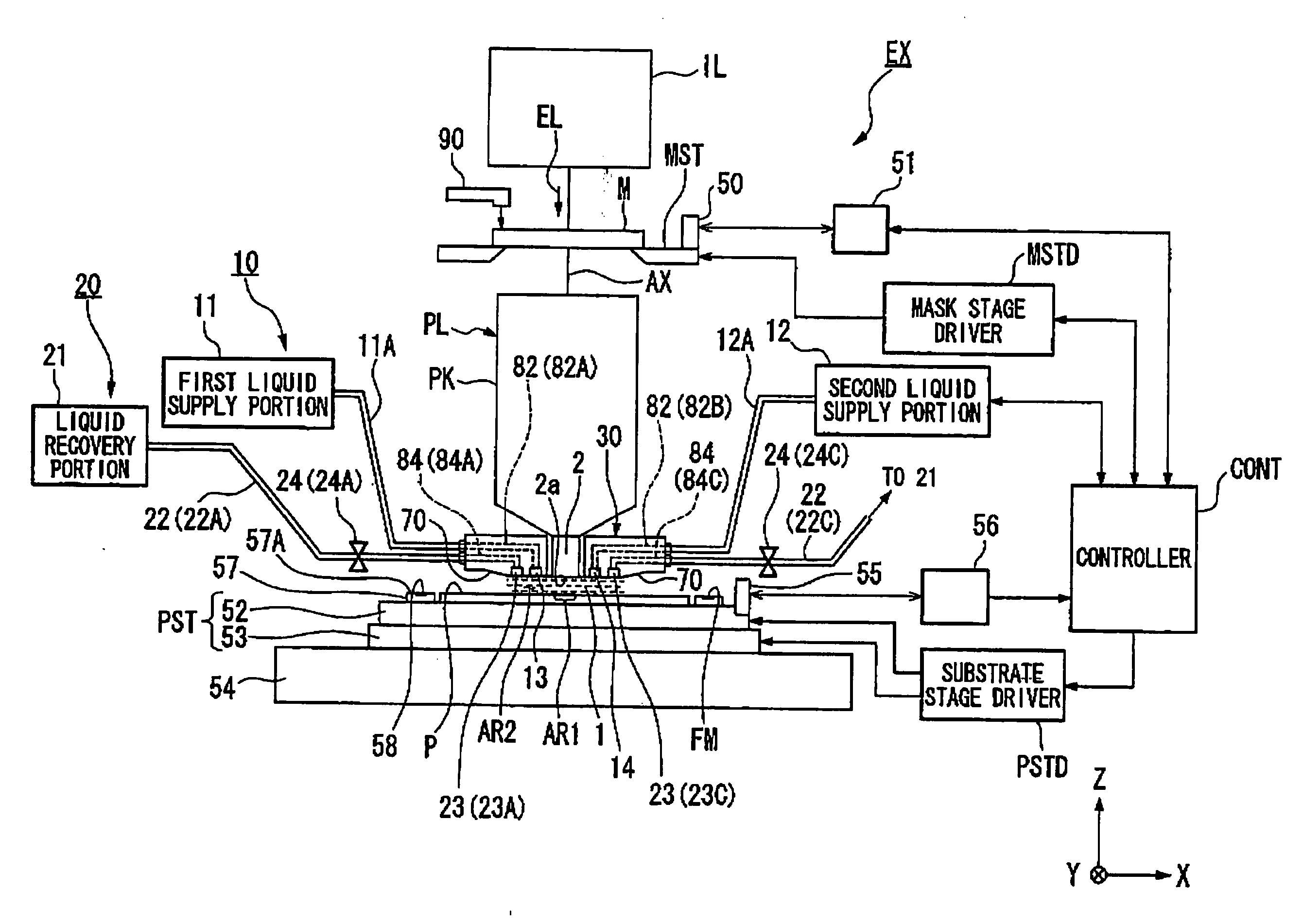
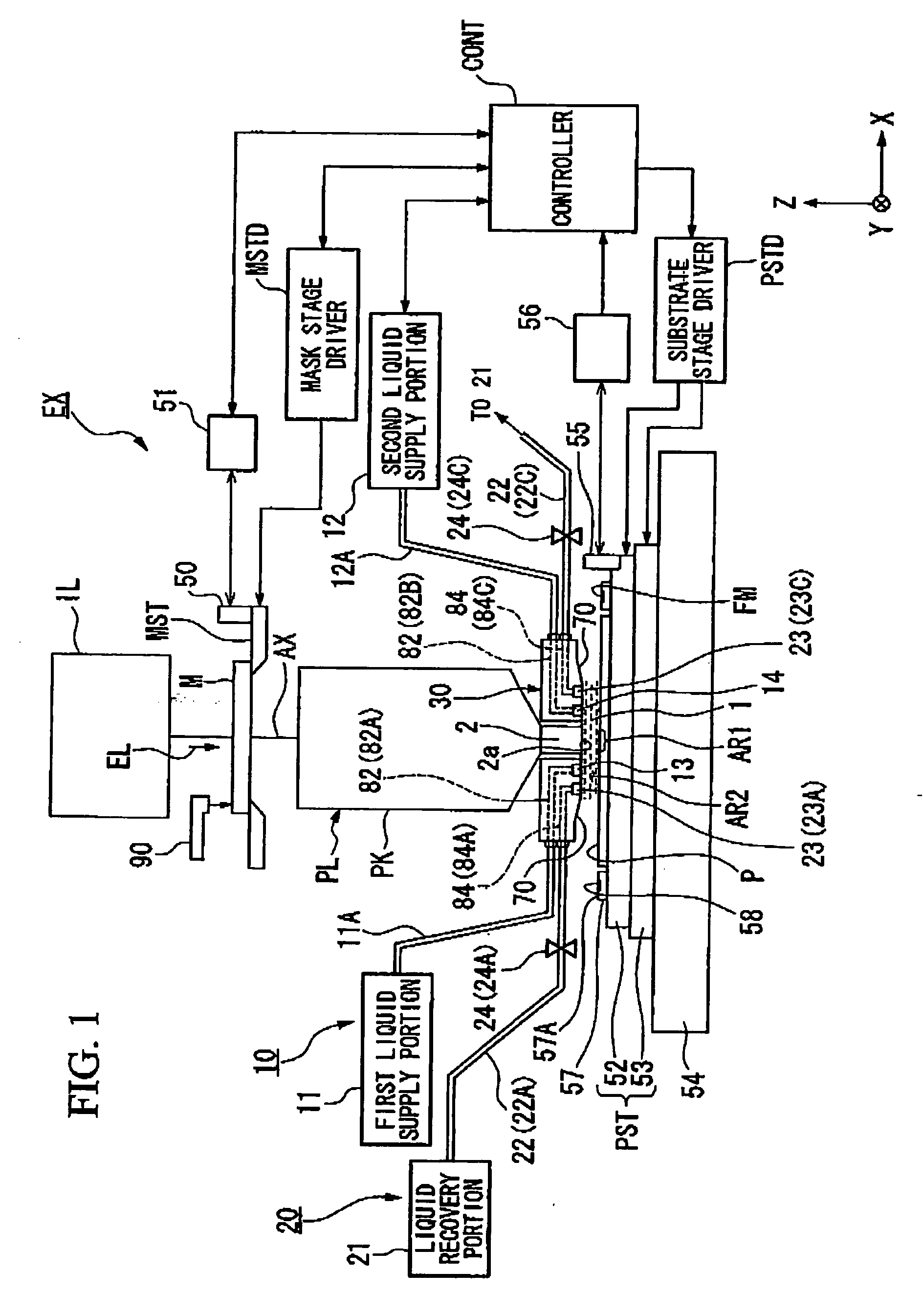
[0043]FIG. 1 is a schematic diagram showing an embodiment of an exposure apparatus of the present invention.

[0044] Referring to FIG. 1 exposure apparatus EX is provided with mask stage MST that supports mask M, substrate stage PST that shorts substrate P, illumination optical system IL that illuminates mask M supported by mask stage MST with exposure light EL, projection optical system EL that projection exposes a pattern image of mask M illuminated with exposure light EL onto substrate P supported by substrate stage PST, and controller CONT that controls the overall operation of exposure apparatus EX.

[0045] Exposure apparatus EX of the embodiment is a liquid immersion exposure appa...


PUM


Abstract

An exposure apparatus that by irradiating an exposure light, via a projection optical system and a liquid, on a substrate placed on the image plane side of the projection optical system, exposes the substrate, the exposure apparatus includes; a liquid supply mechanism that supplies the liquid onto the substrate; a liquid recovery mechanism that recovers the liquid having been supplied on the substrate; and wherein when the exposure light is being irradiated on the image plane side of the projection optical system, the liquid recovery mechanism does not perform the recover of the liquid.

Description

CROSS-REFERENCE TO RELATED APPLICATION [0001] This is a Continuation Application of International Application No. PCT / JP2004 / 012319, filed Aug. 20, 2004, which claims priority to Japanese Patent Application Nos. 2003-297507 (filed Aug. 21, 2003) and 2004-38411 (filed Feb. 16, 2004). The contents of the aforementioned application are incorporated herein by reference.BACKGROUND OF THE INVENTION [0002] 1. Field of the Invention [0003] The present invention relates to an exposure apparatus, an exposure method and a device manufacturing method in which a substrate is, with the substrate being irradiated with an exposure light exposed. [0004] 2. Description of Related Art [0005] Semiconductor devices and liquid crystal display devices manufactured through the so-called photolithography technique, by which a pattern formed on a mask is transferred onto a photoactive substrate. The exposure apparatus used in the photolithography process has a mask stage that supports a mask and a substrate ...

Claims


Application Information

Patent Timeline
IPC IPC(8): G03B27/42G03F7/20H01L21/027
CPCG03F7/2041G03F7/709G03F7/70341H01L21/0274
Inventor NAGASAKA, HIROYUKIISHII, YUUKIMAKINOUCHI, SUSUMU
Owner NIKON CORP
Learn More