Eureka AIR delivers breakthrough ideas for toughest innovation challenges, trusted by R&D personnel around the world.

Carburized component and method of manufacturing the same

a technology of carburized components and manufacturing methods, applied in the direction of solid-state diffusion coatings, coatings, metallic material coating processes, etc., can solve the problems of pitting fracture and insufficient above-described materials to meet the requirements, and achieve the effects of reducing impact strength and fatigue strength of dedendum, and reducing the growth of grain boundary oxide layers

Inactive Publication Date: 2006-06-22
DAIDO STEEL CO LTD +1
View PDF1 Cites 18 Cited by
  • Summary
  • Abstract
  • Description
  • Claims
  • Application Information

AI Technical Summary

Benefits of technology

[0015] Si is an element to be contained as a deoxidizing element acting in the process of melting and plays an important role in this invention. The element dissolves into the solid matrix to thereby raise the temper softening resistance, so that a high level of surface fatigue strength can be obtained. The element can also suppress growth of coarse carbide grains, because it shows only a small solid solubility into the carbide and raises the Si concentration in the base metal. Moreover, under precipitation of a large amount of carbide, Si showing only a small solid solubility into the carbide concentrates in the matrix, and further improves the temper softening resistance of the matrix. The element is necessarily contained to an amount of 0.80% or more in order to obtain this effect. On the other hand, an excessive content of the element inhibits precipitation and the carburization surface reaction of the carbide which thereby distinctively degrades the carburization property, and also degrades the ductility, which thereby makes cracking more likely to occur in the process of plastic working. The upper limit of the content is therefore limited to 1.50%.
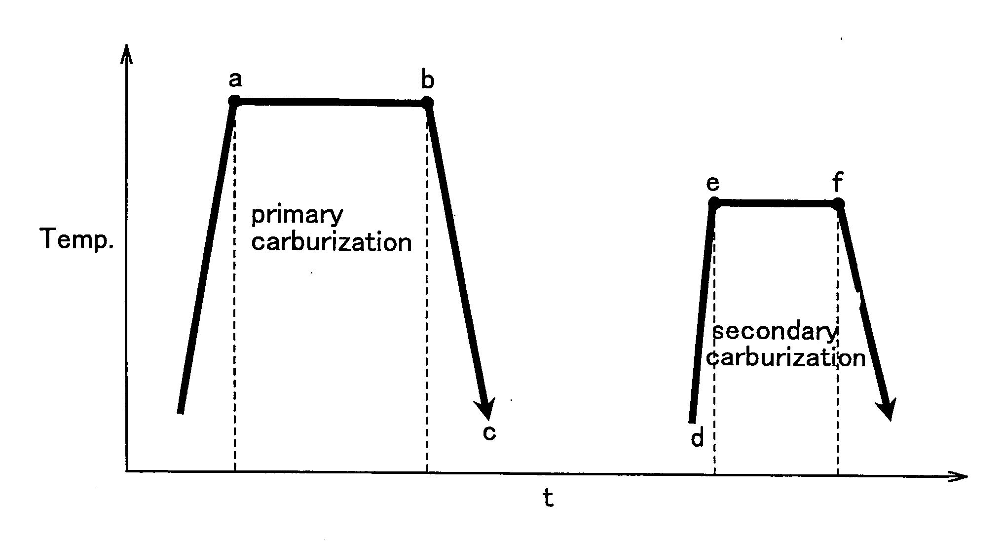
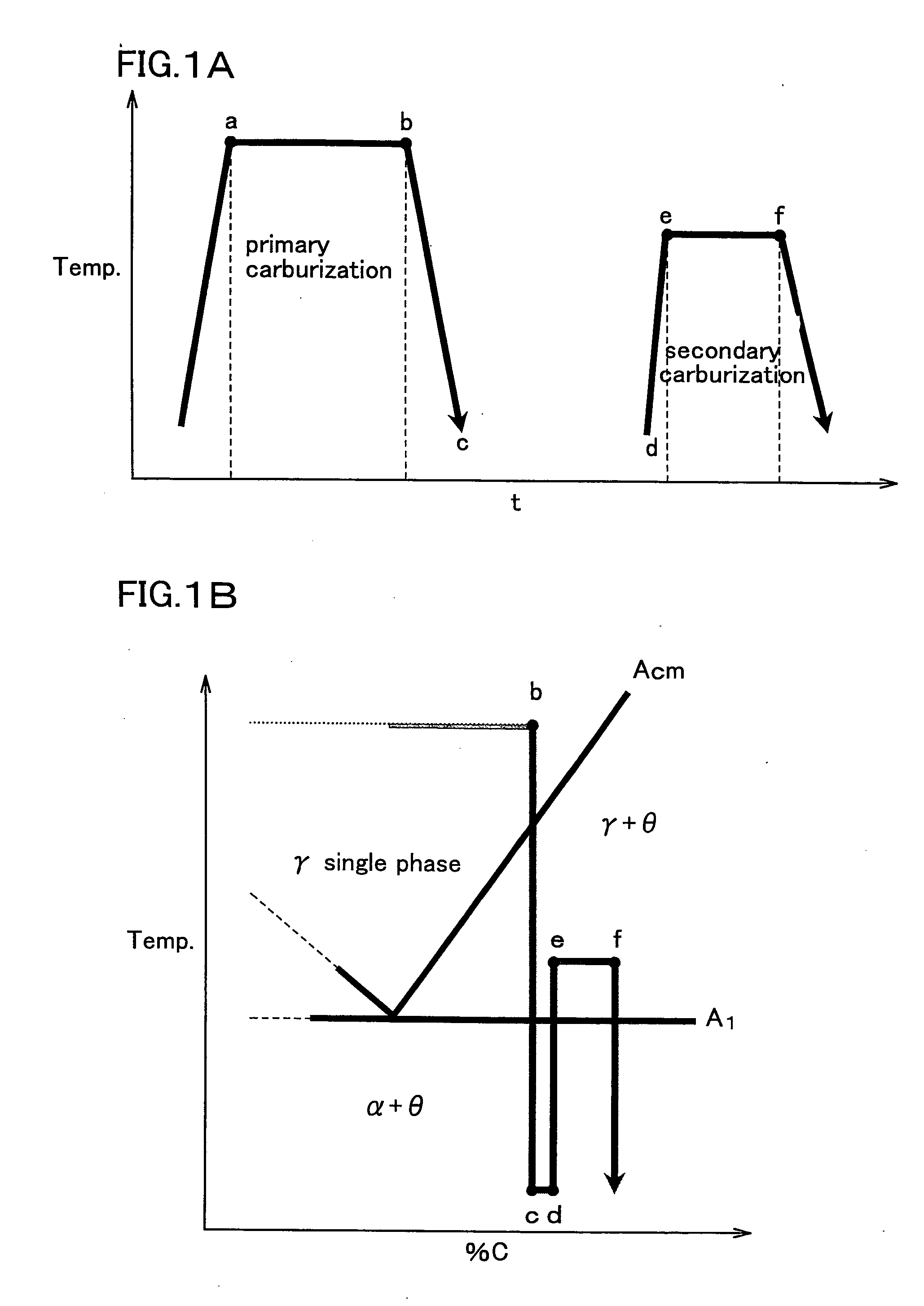
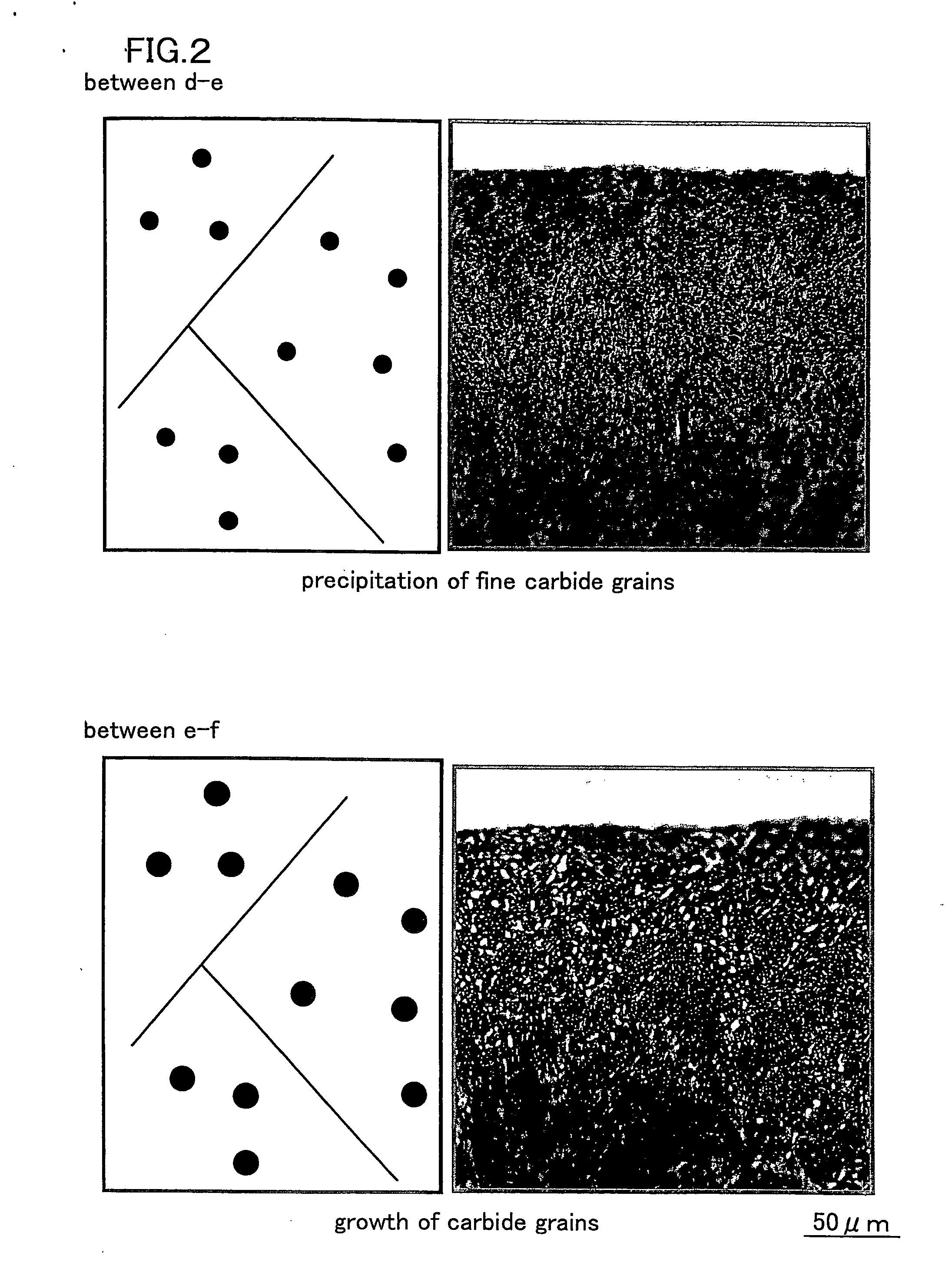
[0037] Aiming at manufacturing the above-described carburized component, a method of manufacturing a carburized component of this invention subjects the steel containing the above-described steel ingredients to a primary carburization at a temperature of Acm or above, then rapidly cools the steel to as low as point A1 or below, and then subjects the steel to a secondary carburization at a temperature of point A1 or above and Acm or below. More specifically, as shown in FIGS. 1A and 1B, the primary carburization is carried out so as not to precipitate the carbide, at a temperature of as high as Acm or above, allowing a large solid solubility limit of C and allowing no carbide to precipitate (between points “a” and “b”). Next, the steel is rapidly cooled so as to dissolve C into a solid super-saturated manner (between points “b” and “c”). Thereafter, the steel is again heated to as high as point A1 or above, to thereby allow fine carbide nuclei to uniformly precipitate from the base material super-saturated with C (between points “d” and “e”, see the upper drawing in FIG. 2), and the steel is further subjected to a secondary carburization so as to grow the nuclei (between points “e” and “f”, see the lower drawing in FIG. 2). Such multi-stage carburization can realize a high-C-concentration carburization with a controlled fine dispersion of the carbide, without allowing the network-structured carbide to precipitate. In contrast to this, as shown in FIG. 3, the carburization carried out to as far as the high-C-concentration region before point Acm makes the network-structured coarse carbide very likely to produce. The carburization therein is carried out by vacuum carburization (at 1,000 Pa or below) as described in the above.

Problems solved by technology

Gears cause slippage on the tooth surface thereof, and the repetitive contact generates heat at the portion just under the tooth surface.
Temperature in this state is known to fall in the range of about 200 to 300° C., and the heat generated herein supposedly softens the material and consequently results in pitting fracture.
The gear has, however, has been demanded to have a larger hardness with the recent increases in the output of automobiles and so forth, but the present situation is that the above-described material is insufficient for fulfilling the requirements.

Method used


Image

  • Carburized component and method of manufacturing the same
  • Carburized component and method of manufacturing the same
  • Carburized component and method of manufacturing the same

Examples


Embodiment Construction

[0043] The following paragraphs will describe tests carried out for confirming the effects of this invention.

[0044] First, each of the steels having chemical compositions listed in Table 1 was melted in a 150-kg high-frequency vacuum induction furnace. The obtained steel ingot was rolled or hot forged so as to produce a 90-mm-diameter round rod, or further hot-forged, if necessary, so as to obtain steel bar shape having a diameter of 22 to 32 mm, which was used as a test piece.

[0045] In the compositions of comparative examples listed in Table 1, those departing from the compositional ranges specified by this invention are indicated by a downward arrow (↓), for those short of the lower limits, an upward arrow (⇑), for those exceeding the upper limits.

TABLE 1CSiMnCrMoVRemarksExample 10.180.980.632.390.000.00Example 20.180.800.502.660.000.00Example 30.191.020.522.520.000.00Example 40.180.970.553.220.000.00Example 50.181.480.552.580.000.00Example 60.191.050.552.120.000.00Example 70....


PUM

PropertyMeasurementUnit
grain sizeaaaaaaaaaa

Abstract

This invention aims to provide a carburized component realizing a larger strength for power transmission components such as gears, and a method of manufacturing the same. The carburized component of this invention, aimed at realizing the object, consists essentially of, in % by mass and both ends inclusive, C: 0.1-0.30%, Si: 0.80-1.50%, Mn: 0.30-1.20%, Cr: 2.0-5.5%, and the balance of Fe and inevitable impurities; has a mean C concentration over the range from the surface of the steel to a depth of 0.2 mm after vacuum carburization of 1.2% or more and 3.0% or less, and has a ratio of a carbide area over the range from the surface to a depth of 50 μm of 15% or more and 60% or less, has the carbide precipitated in a finely dispersed manner so that the carbide having a grain size of 10 μm or less accounts for 90% or more of the entire portion, and has a depth of a grain boundary oxide layer below the surface of 1 μm or less.

Description

FIELD OF THE INVENTION [0001] This invention relates to a carburized component and a method of manufacturing the same. BACKGROUND ART [0002] Gears used as power transmission components for automobiles and so forth are components suffering from dedendum fractures which occur at the dedendum where bending stress happens, and from slip-induced fracture (pitting) which occurs in the vicinity of the pitch point. A technique of carburizing the surface of the component has, therefore, widely been used for the purpose of fulfilling characteristics enough for withstanding harsh conditions, and further improvement has been made by combining various materials and heat treatments. [0003] Particularly in recent years, a successful development has been made on a material capable of suppressing growth of grain boundary oxide layer and abnormally carburized layer during carburization, which are understood as being harmful to dedendum fracture. Another achievement has been made on improvement in the...

Claims


Application Information

Patent Timeline
Patent Type & Authority Applications(United States)
IPC IPC(8): C23C8/22
CPCC23C8/22C23C8/80
Inventor HATTORI, ATSUSHIKANO, TAKASHISERIKAWA, TOMOKOMIZUNO, KOKI
Owner DAIDO STEEL CO LTD
Why Eureka
Eureka Blog
Learn More