Method of using scan chains and boundary scan for power saving
- Summary
- Abstract
- Description
- Claims
- Application Information
AI Technical Summary
Benefits of technology
Problems solved by technology
Method used
Image
Examples
Embodiment Construction
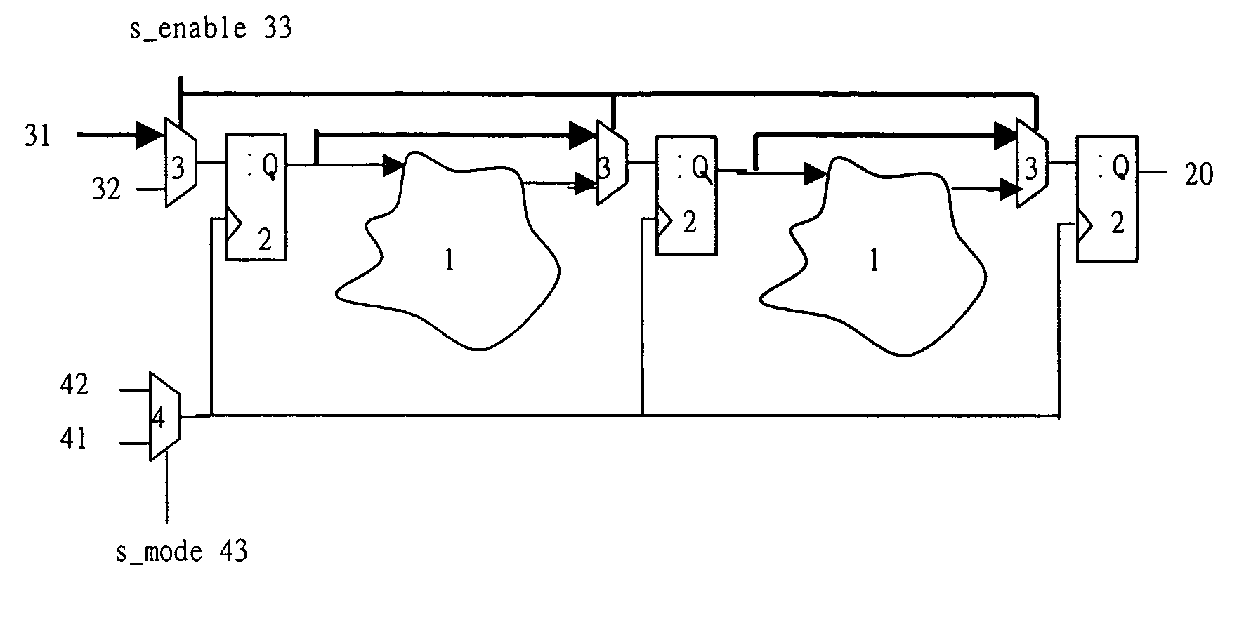
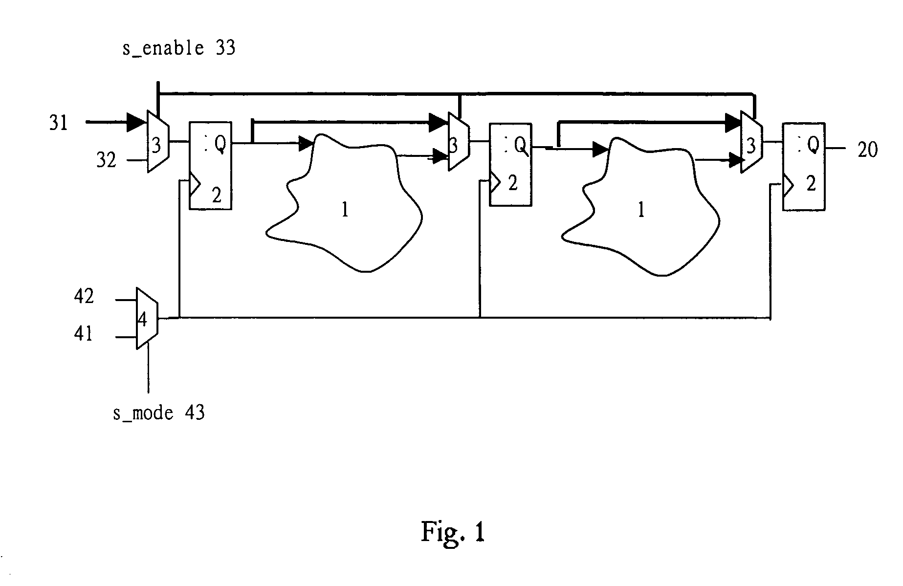
[0031] Referring to the FIG. 1, a typical section of a production test Scan Chains is shown. In a synchronous logic ASIC, Scan Chains circuit will be added along with the main circuit. The main circuit comprises many combinational logic circuits 1 and many memory-type devices 2 (such as flip-flops, shift-registers). Scan Chain circuit comprises mutiplexer 3 and 4. Multiplxer 3 has two inputs “test 31” and “operation 32”, while multiplexer 4 has two inputs “scan clock 41” and “main clock 42”. When the control signals of s_enable 33 and s_mode 43 of the multiplexer 3 and 4 are pulled low, the “operation 32” and “main clock 42” will be inputted to the synchronous logic ASIC for normal operation. When the control signals of s_enable 33 and s_mode43 of the multiplexer 3 and 4 are pulled high, the circuit goes into the scan mode for production test. The scan clock 41 will replace the main clock 42 to be inputted into the synchronous logic ASIC. The data of “test 31” will be shifted into t...
PUM
 Abstract
Description
Claims
Application Information
 - R&D
- Intellectual Property
- Life Sciences
- Materials
- Tech Scout
- Unparalleled Data Quality
- Higher Quality Content
- 60% Fewer Hallucinations
Browse by: Latest US Patents, China's latest patents, Technical Efficacy Thesaurus, Application Domain, Technology Topic, Popular Technical Reports.
© 2025 PatSnap. All rights reserved.Legal|Privacy policy|Modern Slavery Act Transparency Statement|Sitemap|About US| Contact US: help@patsnap.com


