
System and method for analyte sampling and analysis

a body fluid and system technology, applied in the field of non-invasive body fluid sampling and analysis, can solve the problems of limited flow and volume of body fluid that can be transported across the stratum comeum, pain and inconvenience of using blood for frequent monitoring, and certain limitations of force applied to human skin

Inactive Publication Date: 2006-05-04
SONTRA MEDICAL CORP
View PDF9 Cites 36 Cited by
  • Summary
  • Abstract
  • Description
  • Claims
  • Application Information

AI Technical Summary

Benefits of technology

[0028] It is a technical advantage of the present invention that a system, method, and device for non-invasive sampling and analysis of body fluids is disclosed. It is another technical advantage of the present invention that a concentration of an analyte may be measured continuously or periodically.
that a system, method, and device for non-invasive sampling and analysis of body fluids is disclosed. It is another technical advantage of the present invention that a concentration of an analyte may be measured continuously or periodically.

Problems solved by technology

This practice of using blood to perform frequent monitoring can be painful and inconvenient.
For example, these painless methods include the use of tiny needles,
Although these forces can be used for extraction of body fluids, there are certain limitations that may apply when the forces are applied to human skin.
For example, a major limitation is the flow and volume of body fluid that can be transported across the stratum comeum.
The application of vacuum on skin for an extended period may cause physical separation of the epidermis from the dermis, resulting in bruises and blisters.
Another example of a limitation is the amount of energy that can be applied to the skin in order to create convective flow.
Extraction of usable volume of body fluid has the potential to cause pain and skin damage with prolonged exposure to ultrasound.
In a similar manner, electro-osmotic extraction of body fluid through stratum comeum has the potential to cause skin damage due the need to use high current density.
It is evident that there are limitations to the use of the mentioned extraction methods when applied to human skin.

Method used


Image

  • System and method for analyte sampling and analysis
  • System and method for analyte sampling and analysis
  • System and method for analyte sampling and analysis

Examples


example 1

[0114] The following example does not limit the present invention in any way, and is intended to illustrate an embodiment of the present invention.

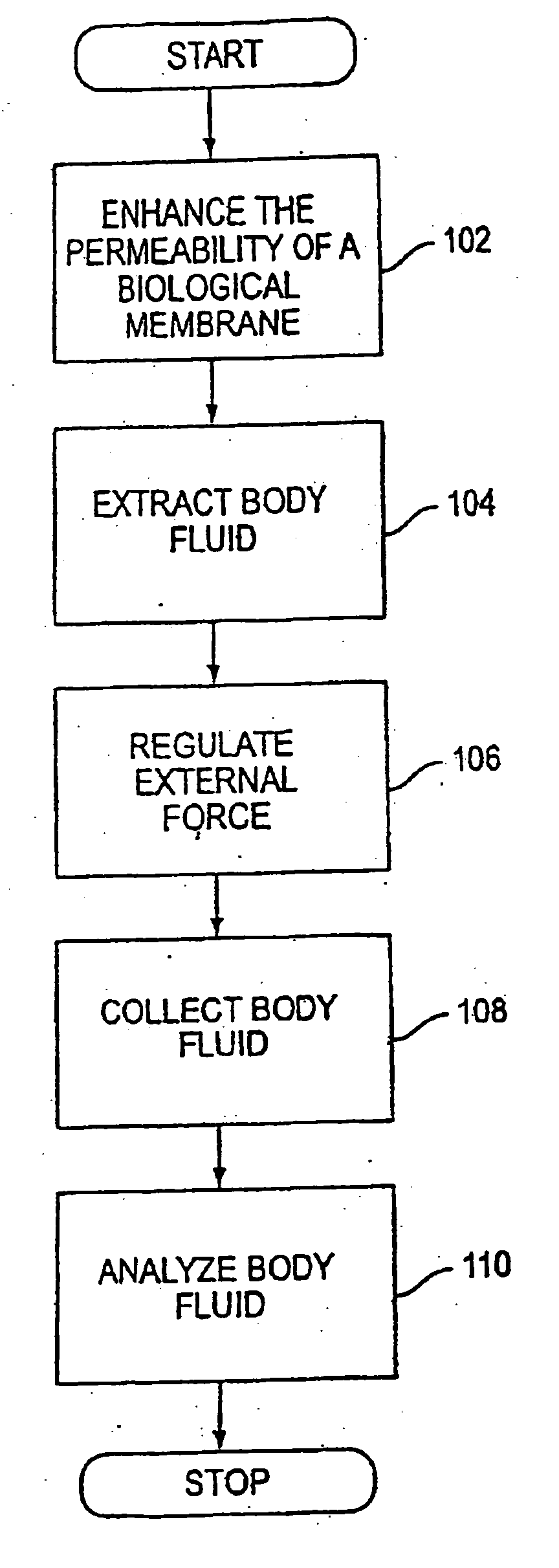
[0115] The following is a description of experiments which implemented painless extraction, collection, and analysis of body fluid to determine body fluid glucose concentration in a human using a hyperosmotic extraction fluid and comparing this condition with iso-osmotic extraction fluid, in accordance with one embodiment of the present invention. Although body fluid glucose concentration serves as an example to demonstrate feasibility, other analytes are within the contemplation of the present invention. In addition, multiple analytes may be measured and / or analyzed simultaneously, in parallel, or in series, and results from these multiple measurements may be used in combination with algorithms, for example, to increase the accuracy or precision or both of measurements. As may be recognized by one of ordinary skill in the art, these ste...

example 2

[0160] Vinyl acetate based hydrogels for use with glucose monitoring can be prepared as follows. A 1:1 mixture of n-vinylpyrolidone and vinyl acetate can be polymerized by ultraviolet radiation using 0-0.5% Irgacure as the photoinitiator. A non-woven plastic scrim (such as Delstar product# RB0707-50P) is used to provide mechanic support. The hydrogel's equilibrium water content is 20-95% with its aqueous composition containing 0-1 M sodium or potassium phosphate, 0-1 M sodium chloride, 0-1 M potassium chloride, 0-2 M lactic acid, surfactant such as 0-1 M Triton X-100, Tween 80 or sodium lauryl sulfate, and any other biocompatible components. Glucose oxidase can be loaded by soaking the solid hydrogel layer in concentrated glucose oxidase solution for a period of time.

[0161] A particular example of a vinyl acetate based hydrogel was made with the following constituents: 15% n-vinylpyrolidone, 15% vinyl acetate, 0.05% Irgacure, 0.05 M potassium phosphate, 0.30 M sodium chloride, 0.02...

example 3

[0163] Agarose based hydrogels for use with glucose monitoring were prepared as follows. 0.0116 g of sodium chloride, 0.015 g of potassium chloride, 0.0348 g of dibasic potassium phosphate and 0.002 g of Triton X-100 were dissolved in 10 mL of water. The pH of the solution was adjusted to 7.0 using 0.5 M hydrochloric acid with the aid of a pH meter. The solution was diluted with water to 20 mL. This was Solution A. 0.2 g of agarose powder was mixed and dispersed in Solution A. Agarose was heated and dissolved until boiling in a water bath. This was Solution B. Solution B was allowed to cool down to 35° C. 0.01 g of glucose oxidase powder was completely mixed and dissolved in Solution B. This was Solution C. Solution C was cast and filled onto a warm, flat mold surface. The mold was transferred to room temperature or lower to form gels.

[0164]FIG. 12 shows sensor signal response as a function of glucose concentration for two types of agarose hydrogels relative to a polyethylene oxide...


PUM

PropertyMeasurementUnit
Concentrationaaaaaaaaaa
Biological propertiesaaaaaaaaaa
Permeabilityaaaaaaaaaa

Abstract

The invention relates to a transdermal analyte monitoring system comprising a medium adapted to interface with a biological membrane and to receive an analyte from the biological membrane and an electrode assembly comprising a plurality of electrodes, wherein the medium is adapted to react continuously with the analyte, an electrical signal is detected by the electrode assembly, and the electrical signal correlates to an analyte value. The analyte value may be the flux of the analyte through the biological membrane or the concentration of the analyte in a body fluid of a subject. The medium may comprise a vinyl acetate based hydrogel, an agarose based hydrogel, or a polyethylene glycol diacrylate (PEG-DA) based hydrogel, for example. The surface region of the electrode may comprise pure platinum. The system may include an interference filter located between the biological membrane and the electrode assembly for reducing interference in the system. The system may comprise a processor programmed to implement an error correction method that corrects for sensor drift.

Description

[0001] The present application is a divisional of U.S. application Ser. No. 11 / 201,334, filed Aug. 11, 2005, which is a continuation of U.S. application Ser. No. 10 / 974,963, filed Oct. 28, 2004, both of which are hereby incorporated by reference in their entireties. The present application is related to the following patent and applications, each of which is incorporated herein by reference it its entirety: U.S. application Ser. No. 09 / 979,096, filed Mar. 16, 2001; U.S. application Ser. No. 09 / 868,442, filed Dec. 17, 1999; U.S. Provisional Application No. 60 / 112,953, filed Dec. 18, 1998; U.S. Provisional Application No. 60 / 142,941, filed Jul. 12, 1999; U.S. Provisional Application No. 60 / 142,950, filed Jul. 12, 1999; U.S. Provisional Application No. 60 / 142,951, filed Jul. 12, 1999; U.S. Provisional Application No. 60 / 142,975, filed Jul. 12, 1999; U.S. Pat. No. 6,190,315; and U.S. Provisional Application No. 60 / 070,813, filed Jan. 8, 1998.BACKGROUND OF THE INVENTION [0002] 1. Field o...

Claims


Application Information

Patent Timeline
IPC IPC(8): A61B5/05C12Q1/54A61B5/00A61B5/296
CPCA61B5/14514Y10T436/144444A61B5/681A61B5/1486C08L33/24G01N27/4166A61B5/14532A61L31/048A61L31/145C08L33/26C08L2203/02G01N27/3273
Inventor BARMAN, SHIKHA P.CHUANG, HAN
Owner SONTRA MEDICAL CORP
Learn More