
Low cost detectible pipe and electric fencing manufactured from conductive loaded resin-based materials

Inactive Publication Date: 2006-05-04
INTEGRAL TECHNOLOGY INC
View PDF8 Cites 21 Cited by
  • Summary
  • Abstract
  • Description
  • Claims
  • Application Information

AI Technical Summary

Benefits of technology

[0014] A further object of the present invention is to provide a locatable pipe that is robust for buried pipe installation.
[0016] A further object of the present invention is to provide an electric fence that is not susceptible to corrosion.
[0017] A further object of the present invention is to provide an electric fence that will work properly even if partially damaged.

Problems solved by technology

Traditional metal detection techniques do not work for PVC pipes.
First, it is relatively easy for the wire to be broken during installation or during subsequent construction events.
If the wire is broken, location techniques may not work properly.
Second, the proper installation of the pipe is made more difficult due to the lack of ruggedness of the locator wire.
The discharge shock is unpleasant for the animal but not sufficient to cause injury.
First, depending on the type of metal wire used, corrosion of the wire surface can reduce shock capability or, in the worst case, create a risk of animal injury.
Second, wire breakage will typically disable the electric shock function of an entire section of fence.

Method used


Image

  • Low cost detectible pipe and electric fencing manufactured from conductive loaded resin-based materials
  • Low cost detectible pipe and electric fencing manufactured from conductive loaded resin-based materials
  • Low cost detectible pipe and electric fencing manufactured from conductive loaded resin-based materials

Examples


second embodiment

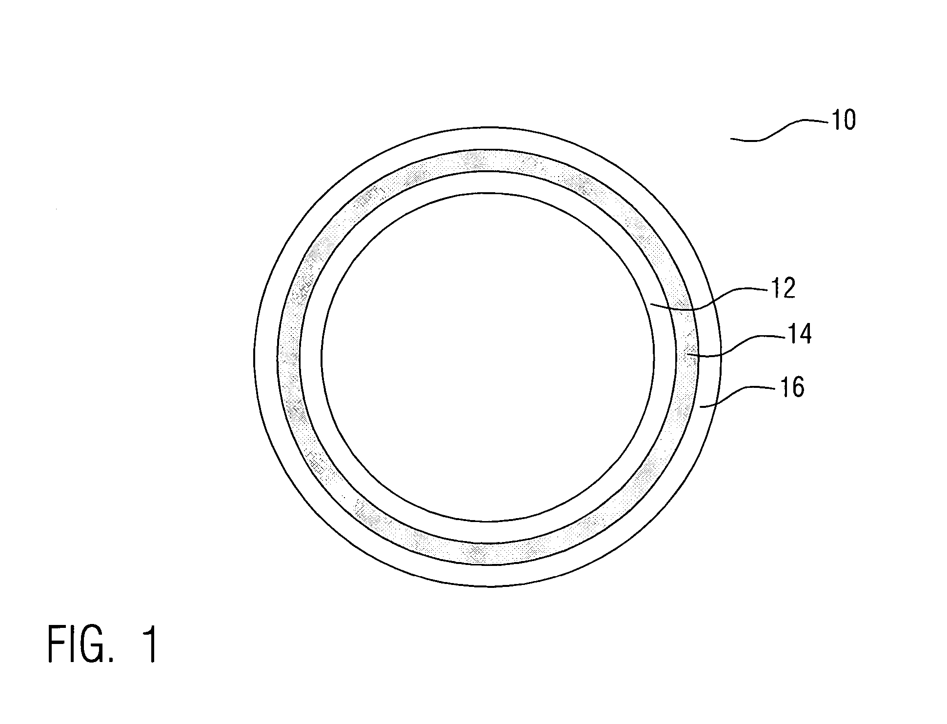
[0078] Referring now to FIG. 7, a second preferred embodiment of the present invention is illustrated. Another pipe 90 is shown in cross-sectional representation. In this embodiment the pipe 90 comprises, in part, the conductive loaded resin-based material of the present invention. In particular, the pipe 90 comprises an inner layer 92 of a non conductive resin-based material such as PVC and a conductive layer 94 of the conductive loaded resin-based material of the present invention. In one embodiment, the pipe 90 is formed by co-extruding the conductive layer 94 of the conductive loaded resin-based material of the present invention with the inner layer 92 of non conductive resin-based material. In another embodiment, the pipe 90 is formed by over-molding the conductive layer 94 of the conductive loaded resin-based material onto the inner layer 92 of non conductive resin-based material. The novel pipe 90 in this embodiment shares the same capability for underground detection as the ...

embodiment 300

[0087] Referring now to FIG. 19, a fourteenth preferred embodiment 300 of the present invention is shown in cross section. A conductor 300 for an electric fence is illustrated. The conductor 300 is formed of the conductive loaded resin-based material of the present invention. In traditional electric fence systems, a metal wire is used. Typically, to keep costs low, a steel wire is used. While steel wire is inexpensive and strong, it suffers the disadvantages of relatively high resistance and of corrosion. Alternatively, an aluminum wire is sometimes used to eliminate corrosion and to reduce resistance. However, aluminum increases cost and can easily break.

[0088] In the present invention, the electric fence conductor 302 comprises the conductive loaded resin-based material. The conductive loaded resin-based material offers several advantages. A low resistance conductor is achieved without a metal wire. The conductor is not susceptible to corrosion. Therefore, the performance degradat...


PUM


Abstract

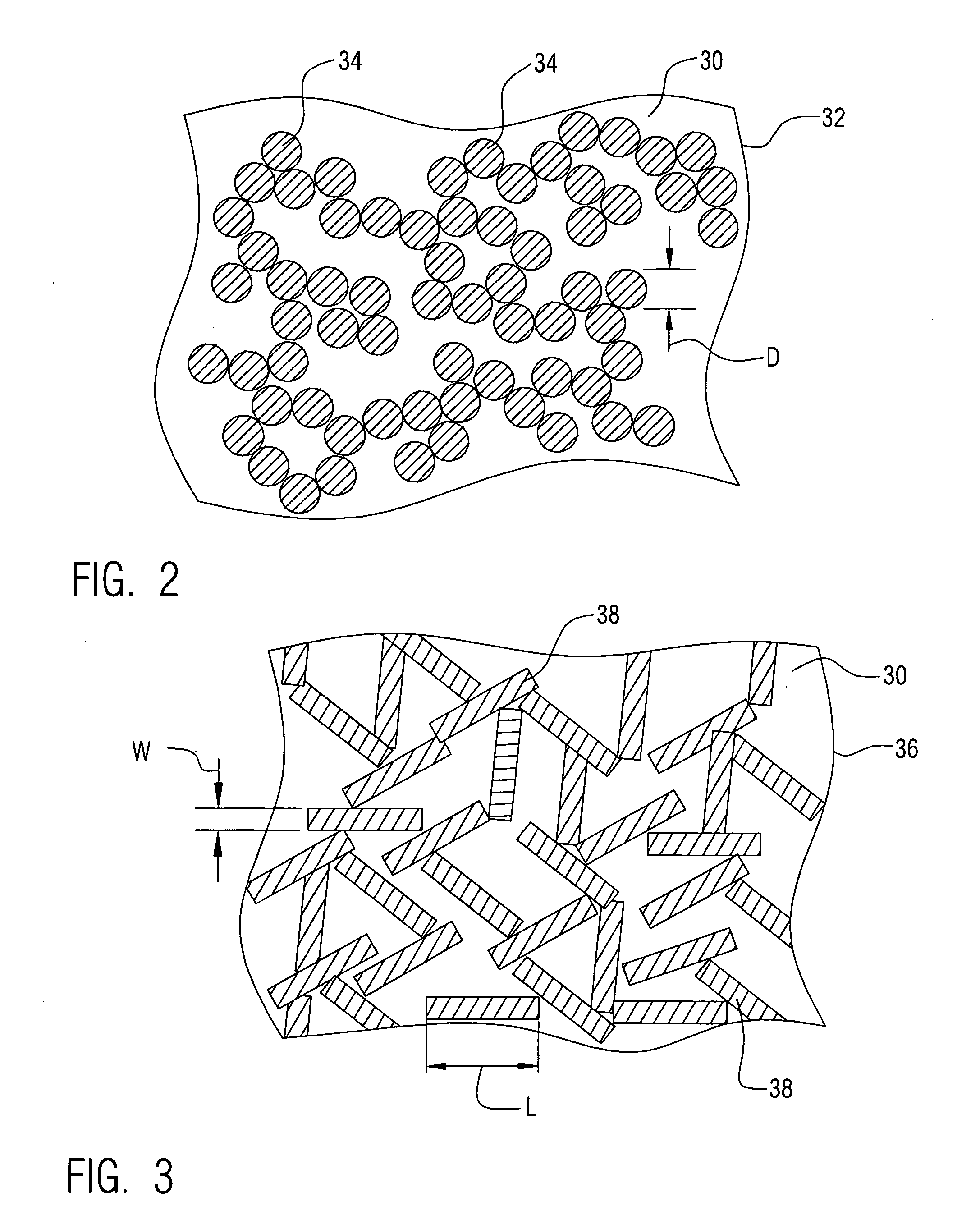
Detectable pipe and electric fence are formed of a conductive loaded resin-based material. The conductive loaded resin-based material comprises micron conductive powder(s), conductive fiber(s), or a combination of conductive powder and conductive fibers in a base resin host. The percentage by weight of the conductive powder(s), conductive fiber(s), or a combination thereof is between about 20% and 50% of the weight of the conductive loaded resin-based material. The micron conductive powders are metals or conductive non-metals or metal plated non-metals. The micron conductive fibers may be metal fiber or metal plated fiber. Further, the metal plated fiber may be formed by plating metal onto a metal fiber or by plating metal onto a non-metal fiber. Any platable fiber may be used as the core for a non-metal fiber. Superconductor metals may also be used as micron conductive fibers and / or as metal plating onto fibers in the present invention.

Description

RELATED PATENT APPLICATIONS [0001] This patent application claims priority to the U.S. Provisional Patent Application Ser. No. 60 / 638,082 filed on Dec. 21, 2004, and the U.S. Provisional Patent Application Ser. No. 60 / 630,587 filed on Nov. 24, 2004, which are herein incorporated by reference in their entirety. [0002] This Patent application is a Continuation-in-Part of INT01-002CIPC, filed as U.S. patent application Ser. No. 10 / 877,092, filed on Jun. 25, 2004, which is a Continuation of INT01-002CIP, filed as U.S. patent application Ser. No. 10 / 309,429, filed on Dec. 4, 2002, now issued as U.S. Pat. No. 6,870,516, also incorporated by reference in its entirety, which is a Continuation-in-Part application of docket number INT01-002, filed as U.S. patent application Ser. No. 10 / 075,778, filed on Feb. 14, 2002, now issued as U.S. Pat. No. 6,741,221, which claimed priority to U.S. Provisional Patent Applications Ser. No. 60 / 317,808, filed on Sep. 7, 2001, Ser. No. 60 / 269,414, filed on F...

Claims


Application Information

Patent Timeline
IPC IPC(8): G01V3/00G08B13/24
CPCA01K3/005G01V3/00G01V13/00F16L1/11F16L9/125
Inventor AISENBREY, THOMAS
Owner INTEGRAL TECHNOLOGY INC
Learn More