
Multilayer coil component

a multi-layer coil and coil body technology, applied in the direction of transformer/inductance details, fixed inductances, inductances, etc., can solve the problem of the risk of the tombstone phenomenon being more likely to occur

Pending Publication Date: 2021-06-17
MURATA MFG CO LTD
View PDF0 Cites 0 Cited by
  • Summary
  • Abstract
  • Description
  • Claims
  • Application Information

AI Technical Summary

Benefits of technology

The patent allows for a creation of a multilayer coil component that does not experience the tombstone phenomenon when being mounted.

Problems solved by technology

Therefore, in the case of the common mode noise filter disclosed in Japanese Unexamined Patent Application Publication No. 2019-36698 as well, there is a risk of the tombstone phenomenon being more likely to occur when the common mode noise filter is reduced in size and consequently dead weight.

Method used


Image

  • Multilayer coil component
  • Multilayer coil component
  • Multilayer coil component

Examples


example 1

[0108]A multilayer coil component of example 1 was manufactured using the following method.

[0109]Preparation of Glass Ceramic Material

[0110]K2O, B2O3, SiO2, and Al2O3 were weighed at a prescribed ratio and mixed in a platinum crucible. Then, the resulting mixture was melted by being fired at a temperature in a range substantially from 1500 to 1600° C. After that, a glass material was prepared by quenching the obtained melted material.

[0111]Next, glass powder was prepared by pulverizing the glass material so that the average particle diameter D50 lay in a range substantially from 1 μm to 3 μm. In addition, quartz powder and alumina powder both having an average particle diameter D50 in a range substantially from 0.5 μm to 2.0 μm were prepared as fillers. Here, the average particle diameter D50 is a particle diameter corresponding to a volume-based cumulative percentage of 50%. Next, a glass ceramic material was prepared by adding the quartz and alumina powders as fillers to the glass...

example 2

[0130]A multilayer coil component of example 2 was manufactured in the same way as the multilayer coil component of example 1 except that the following specifications were adopted.

[0131]The radii of curvature of the first edge portion and the second edge portion were 18 μm.

example 3

[0132]A multilayer coil component of example 3 was manufactured in the same way as the multilayer coil component of example 1 except that the following specification was adopted.

[0133]The radii of curvature of the first edge portion and the second edge portion were 20 μm.


PUM

PropertyMeasurementUnit
dead weightaaaaaaaaaa
distanceaaaaaaaaaa
widthaaaaaaaaaa

Abstract

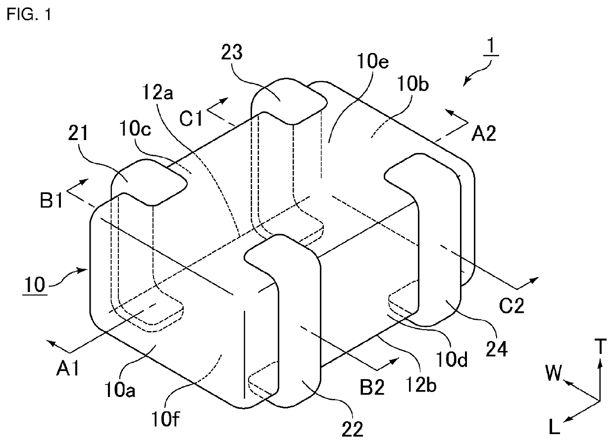
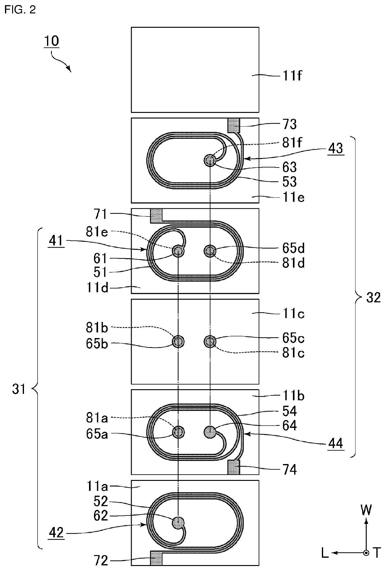
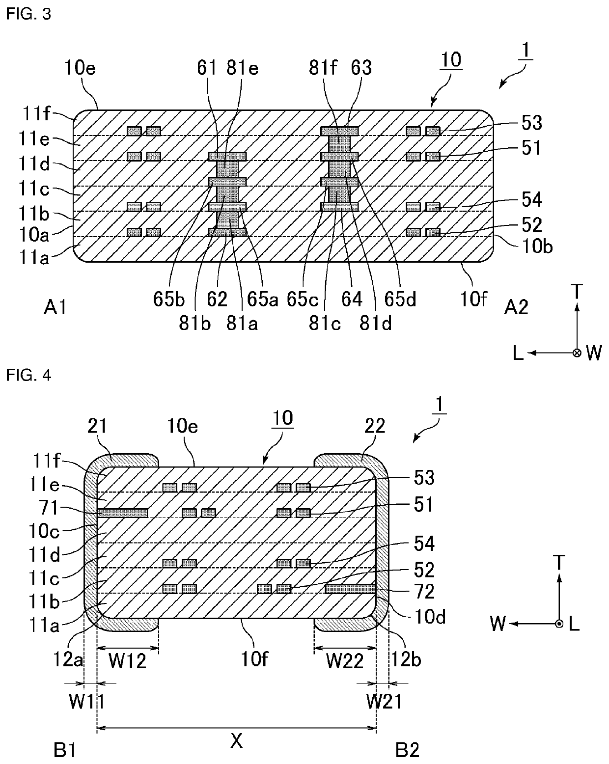
A multilayer coil component includes an element body formed by stacking a plurality of insulating layers on top of one another, a coil buried inside the element body, and an outer electrode that is electrically connected to the coil. The dead weight of the multilayer coil component lies in a range from 0.2 mg to 0.35 mg. The element body has a mounting surface and has a coil lead-out surface to which the coil is electrically led out and on which the outer electrode is provided. Looking at a cross section of the element body that is perpendicular to the mounting surface and the coil lead-out surface, a radius of curvature of an edge portion where the mounting surface and the coil lead-out surface intersect lies in a range from 13 μm to 30 μm.

Description

CROSS-REFERENCE TO RELATED APPLICATION[0001]This application claims benefit of priority to Japanese Patent Application No. 2019-225665, filed Dec. 13, 2019, the entire contents of which is incorporated herein by reference.BACKGROUNDTechnical Field[0002]The present disclosure relates to a multilayer coil component.Background Art[0003]As an example of a multilayer coil component, for example, Japanese Unexamined Patent Application Publication No. 2019-36698 discloses a common mode noise filter that includes a plurality of rectangular insulator layers, first and second coils formed on the insulator layers, a rectangular-parallelepiped-shaped multilayer body including the insulator layers and the first and second coils, and first to fourth outer electrodes formed on the outside of the multilayer body.[0004]Generally, a multilayer coil component has a pair of outer electrodes that are electrically connected to a single coil and the multilayer coil component is mounted on a wiring substra...

Claims


Application Information

Patent Timeline
Patent Type & Authority Applications(United States)
IPC IPC(8): H01F27/29H01F27/32H01F17/00
CPCH01F27/292H01F2017/0093H01F17/0013H01F27/324H01F17/02
Inventor MATSUURA, KOUHEI
Owner MURATA MFG CO LTD
Learn More