Process for producing luminant excitable with vacuum ultraviolet radiation, luminant excitable with vacuum ultraviolet radiation and luminous element including the same

a technology of vacuum ultraviolet radiation and luminant, which is applied in the direction of discharge tube luminescent screen, gas-filled discharge tube, luminescent composition, etc., can solve the problems of low purity, high power consumption, and lower luminous efficiency of pdp's compared to crt's, so as to reduce the amount of defects, increase crystallinity, and reduce heat degradation

Inactive Publication Date: 2006-05-04
NAT INST OF ADVANCED IND SCI & TECH +1
View PDF0 Cites 2 Cited by
  • Summary
  • Abstract
  • Description
  • Claims
  • Application Information

AI Technical Summary

Benefits of technology

[0024] The present inventors have conducted intensive research into reducing heat degradation and VUV deterioration of VUV-excited luminescent material contained in the phosphor layer of plasma display panels. This resulted in the discovery that by increasing crystallinity (in other words, reducing the amount of defects) and having spherical fine particles of small particle size, the VUV-excited luminescent material has improved heat stability and improved stability with respect to vacuum ultraviolet radiation. The present invention was completed based on these discoveries.

Problems solved by technology

In general, PDP's have a lower luminous efficiency as compared to CRT's, and power consumption is high.
The VUV-excited luminescent material particles of the prior art contain impurities, and therefore, their purity is low.
As a result, they are unstable with respect to heat and vacuum ultraviolet radiation, and this is thought to cause heat degradation and VUV deterioration.
However, it is difficult to obtain perfectly spherical alumina particles, and this increases the cost.
On top of this, the luminous brightness of BAM obtained by the solid phase method is low, and it is difficult to reduce heat degradation and VUV deterioration.
In addition, the mixing of impurities can result in heat degradation and VUV deterioration.
In this manner, there are no successful examples of improvements in the crystallinity of the VUV-excited luminescent material and in reducing of the particle size and in controlling the particle shape.

Method used


Image

  • Process for producing luminant excitable with vacuum ultraviolet radiation, luminant excitable with vacuum ultraviolet radiation and luminous element including the same
  • Process for producing luminant excitable with vacuum ultraviolet radiation, luminant excitable with vacuum ultraviolet radiation and luminous element including the same
  • Process for producing luminant excitable with vacuum ultraviolet radiation, luminant excitable with vacuum ultraviolet radiation and luminous element including the same

Examples


embodiment 1

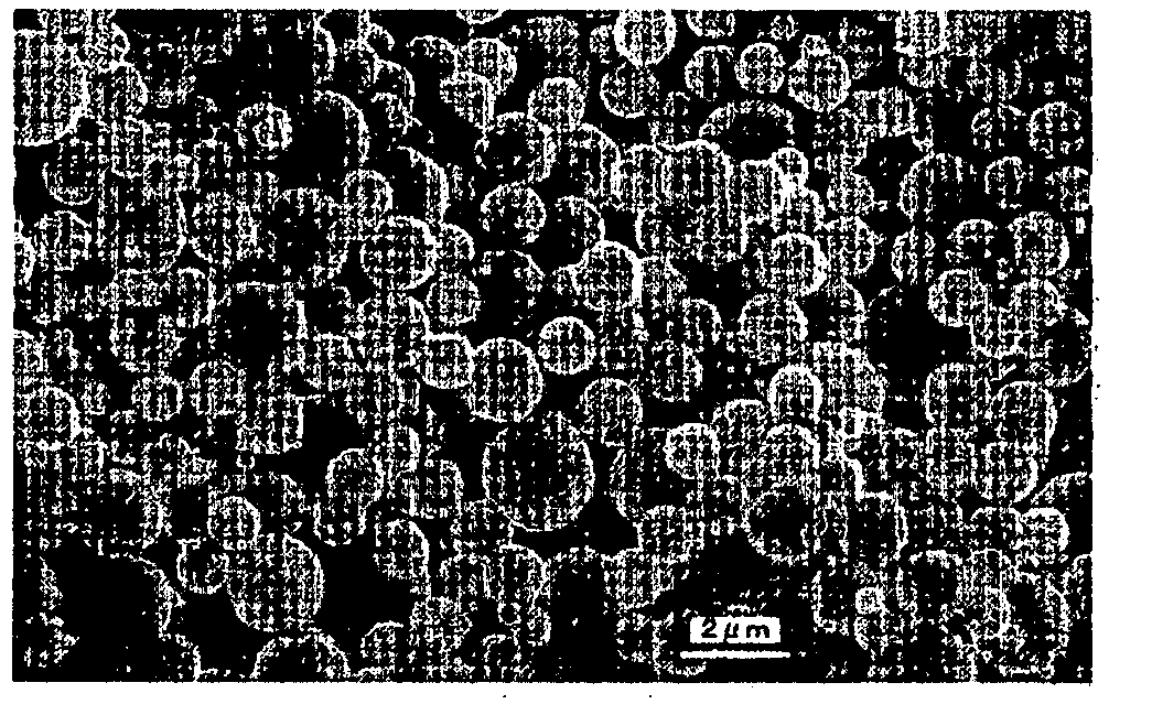
[0124] (1) A raw material solution was obtained by dissolving 0.018 mol of barium nitrate (Ba(NO3)2), 0.02 mol of Mg(NO3)2—6H2O, 0.2 mol of Al(NO3)3—9H2O, 0.002 mol of Eu(NO3)3—2.4H2O in 1 L of distilled water. This raw material solution was introduced into a microchannel atomizing device at a rate of 100 mL per hour and was atomized as a micromist. Together with 5% Ar—N2 gas, this was introduced into a tubular electric furnace set at 1300 degrees C. This was heated for 3 seconds while passing through (reaction step). The resulting spherical fine particles were collected by a collection apparatus. With electron microscope observation and particle distribution analysis, the resulting particles were seen to be truly spherical with average particle diameter D50 of 1.0 micrometers.

[0125] The luminous intensity when the luminescent particles are used in a plasma display is shown in Table 1. In the table, heat degradation was evaluated as the maintenance rate of luminous intensity after ...

embodiment 2

Example of Ultrasonic Type Atomizer

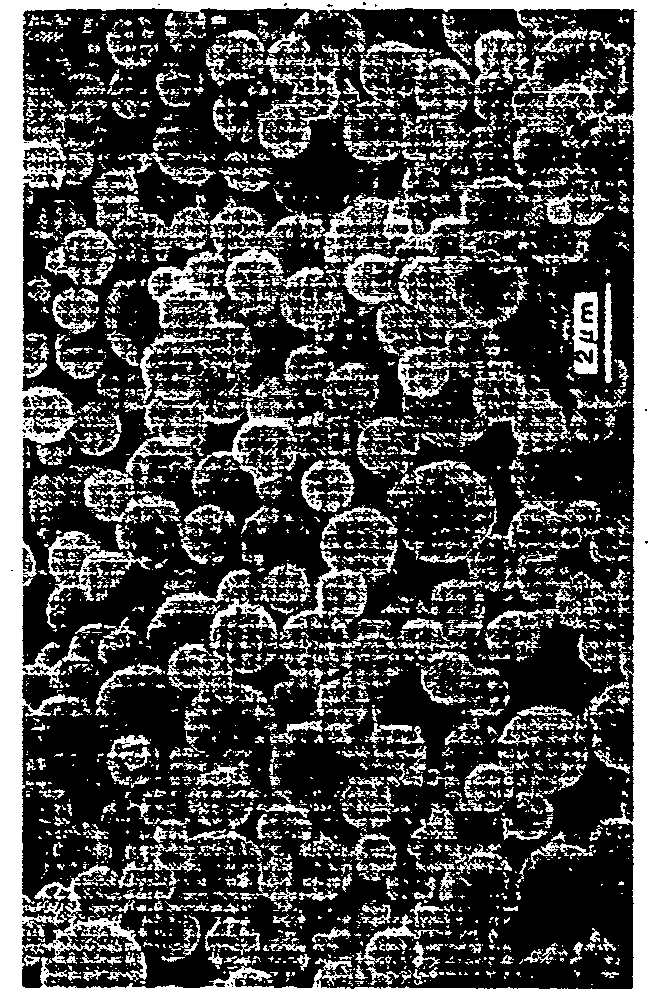
[0135] A raw material solution was obtained by dissolving 0.18 mol of barium acetate (Ba(CH3COO)2), 0.2 mol of Mg(NO3)2—6H2O, 2 mol of Al(NO3)3—9H2O, 0.02 mol of Eu(NO3)3—2.4 H2O in 3 L of distilled water. This raw material solution was introduced into an ultrasonic atomizing device at a speed of 200 mL / hour and was atomized to a micromist. Together with 5% H2—N2 gas, the micromist was introduced into a tubular electric furnace set at 1300 degrees, and reaction baking was conducted. The resulting spherical fine particles were collected with a collection apparatus and maintained at 100 degrees. The resulting particles were spherical with an average particle size of 1.0 micrometers.

[0136] Even with a very short baking time (seconds), the spherical fine particles had a luminous intensity of 60% or greater immediately after atomization. With similar baking times, ones produced by the solid phase reaction method did not emit any light.

[0137] In this ...

embodiment 3

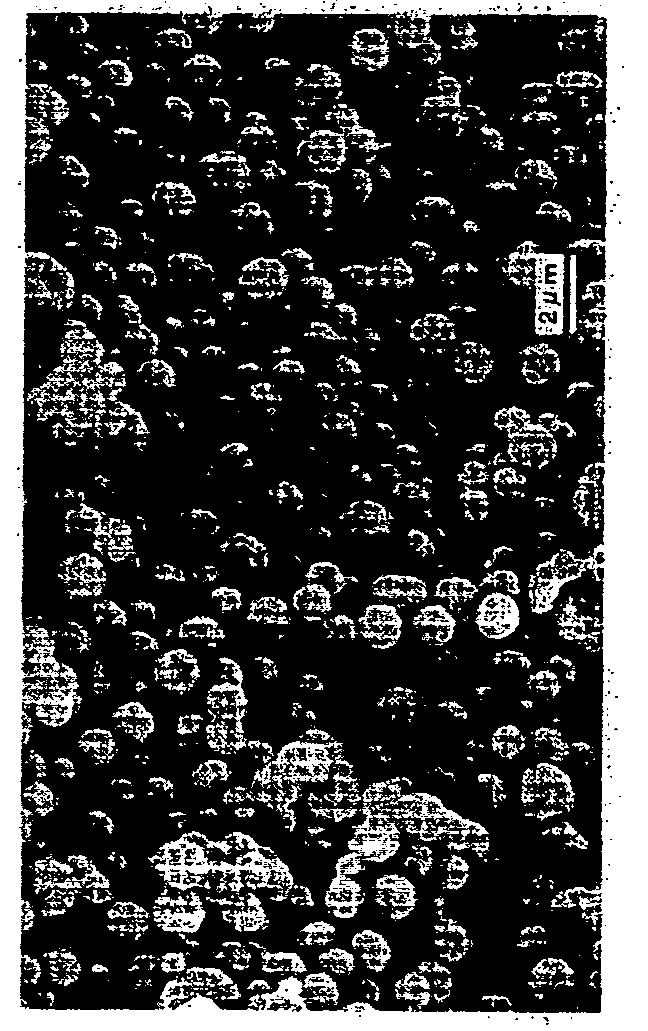
[0139] A raw material solution was obtained by dissolving 0.018 mol of barium nitrate (Ba(NO3)2), 0.02 mol of Mg(NO3)2—6H2O, 0.2 mol of Al(NO3)3—9H2O, 0.002 mol of Eu(NO3)3—2.4 H2O in 3 L of distilled water. This raw material solution was introduced into an ultrasonic atomizing device at a speed of 200 mL / hour and was atomized to a micromist. Together with 5% H2—N2 gas, the micromist was introduced into a tubular electric furnace set at 1300 degrees, and reaction baking was conducted. The resulting spherical fine particles were collected with a collection apparatus and maintained at 100 degrees. The resulting particles were spherical with an average particle size of 0.5 micrometers. After re-baking, the particle size was slightly smaller than after atomization and was 0.45 micrometers. The luminous properties were similarly improved (see Table 1).

Embodiment 4 an Example Using AlF3

[0140] A raw material solution was obtained by dissolving 0.018 mol of barium nitrate (Ba(NO3)2), 0.02...


PUM

PropertyMeasurementUnit
particle sizeaaaaaaaaaa
densityaaaaaaaaaa
pore sizeaaaaaaaaaa

Abstract

A plasma display panel having its thermal degradation and VUV deterioration reduced through enhancement of the crystallinity of luminant excitable with vacuum ultraviolet radiation to thereby attain an enhancement of luminous efficiency; and a process for producing the same. The plasma display panel comprises a pair of opposite arranged substrates and, interposed therebetween, a phosphor layer that is excited with vacuum ultraviolet radiation to thereby emit light, the phosphor layer containing spherical fine particles of a luminant excitable with vacuum ultraviolet radiation. The luminant is composed only of a matrix substance and an activator and is highly pure without having any impurity phase. Accordingly, the phosphor layer can be formed while maintaining the luminance of luminant excitable with vacuum ultraviolet radiation, so that the luminescence intensity of phosphor layer can be enhanced. Thus, there can be provided a plasma display of high luminance.

Description

BACKGROUND OF THE INVENTION [0001] 1. Field of the Invention [0002] The present invention relates to a luminescent material that is excited by vacuum ultraviolet radiation (VUV) and a process for producing the same. The present invention also relates to a luminous element that uses the same. Described in more detail, the present invention relates to a plasma display panel having a phosphor layer containing spherical fine particles of vacuum ultraviolet radiation (VUV)-excited luminescent material and a process for producing the same. The present invention also relates to spherical fine particles of VUV-excited luminescent material which is suitable for use in a phosphor layer of a plasma display panel, and a process for producing the same. [0003] 2. Background Art [0004] With the arrival of the information age, there has been greater demand for large flat displays which are thin and flat. There has been much attention given to plasma display panels (PDP). PDP's are well-suited for i...

Claims


Application Information

Patent Timeline
Patent Type & Authority Applications(United States)
IPC IPC(8): H01J17/49C09K11/64C09K11/08C09K11/77H01J1/63H01J11/22H01J11/34H01J11/42
CPCC09K11/7734H01J1/63H01J2211/42
Inventor XU, CHAONANSHI, WENSHENGNISHIKUBO, KEIKOZHANG, SHUXIUOBATA, MICHIOTANNO, HIROAKI
Owner NAT INST OF ADVANCED IND SCI & TECH
Why Eureka
Try Eureka