Apparatus and method for face cooling of optical components of a laser system

a laser system and optical component technology, applied in the direction of laser cooling arrangements, laser details, instruments, etc., can solve the problems of significant heat load on the transmitting optical components used in high-average power (hap) lasers, thermal aberrations that distort the laser beam, and severely limit the aperture size and power loading allowed in the design of the laser system. achieve the effect of high average power (hap) laser

Inactive Publication Date: 2006-04-27
THE BOEING CO
View PDF43 Cites 23 Cited by
  • Summary
  • Abstract
  • Description
  • Claims
  • Application Information

AI Technical Summary

Benefits of technology

[0011] The present invention is directed to a heat sink assembly ideally suited for face cooling a optical transmissive component (TOC) receiving a laser beam in a high average power (HAP) laser system. The heat sink assembly enables cooling of the TOC without introducing temperature gradients along the TOC in a direction normal to the direction of propagation of the laser beam. The heat sink assembly of the present invention further accomplishes this without the need for physically bonding the TOC to the heat sink assembly.

Problems solved by technology

Transmissive optical components used in high-average power (HAP) lasers experience significant heat load due to absorption of optical energy and other processes.
This creates several problems.
In general, temperature gradients generate thermal-optical stress and index variations, which in turn cause thermal aberrations that distort the laser beam.
The presence of a thermal gradient in this direction severely limits the aperture size and the power loading allowed in a laser system design.
However, this method is not practical in all applications and requires a relatively high degree of complexity in the associated optics.
The chief disadvantage of this method is that it requires a complex, active cooling system, and is therefore less suitable for applications requiring low cost, weight and volume, and a high degree of reliability.
Also the engineering to implement this method is complex because the gas flow across the optical surfaces must be very uniform to avoid optical distortion.
It is well known, however, that transmissive optical components exposed to thermal load tend to warp significantly.
Unless an external force is provided, the effective contact area in mechanically and optically contacted joints is, therefore, significantly reduced, which typically leads to increased temperatures and warpage.
Bonded joints typically use organic adhesive which has a low thermal conductivity and, therefore, impedes effective heat transfer.
In addition, bonded joints cause increased stresses in the transmissive optical component since its transverse thermal expansion is now constrained by attachment to a heat sink.
Finally, heat conduction through narrow gas-filled gaps is rather limited even when gasses with high thermal conductivity are used.

Method used


Image

  • Apparatus and method for face cooling of optical components of a laser system
  • Apparatus and method for face cooling of optical components of a laser system
  • Apparatus and method for face cooling of optical components of a laser system

Examples


Embodiment Construction

[0027] The following description of the preferred embodiment(s) is merely exemplary in nature and is in no way intended to limit the invention, its application, or uses.

[0028] The invention discloses a method for cooling optical components of a high average power, solid state laser (HAPSSL), and thus increasing the power-handling capability of the optical components. The various preferred embodiments enable many tactical and strategic laser systems which would otherwise be too costly to manufacture.

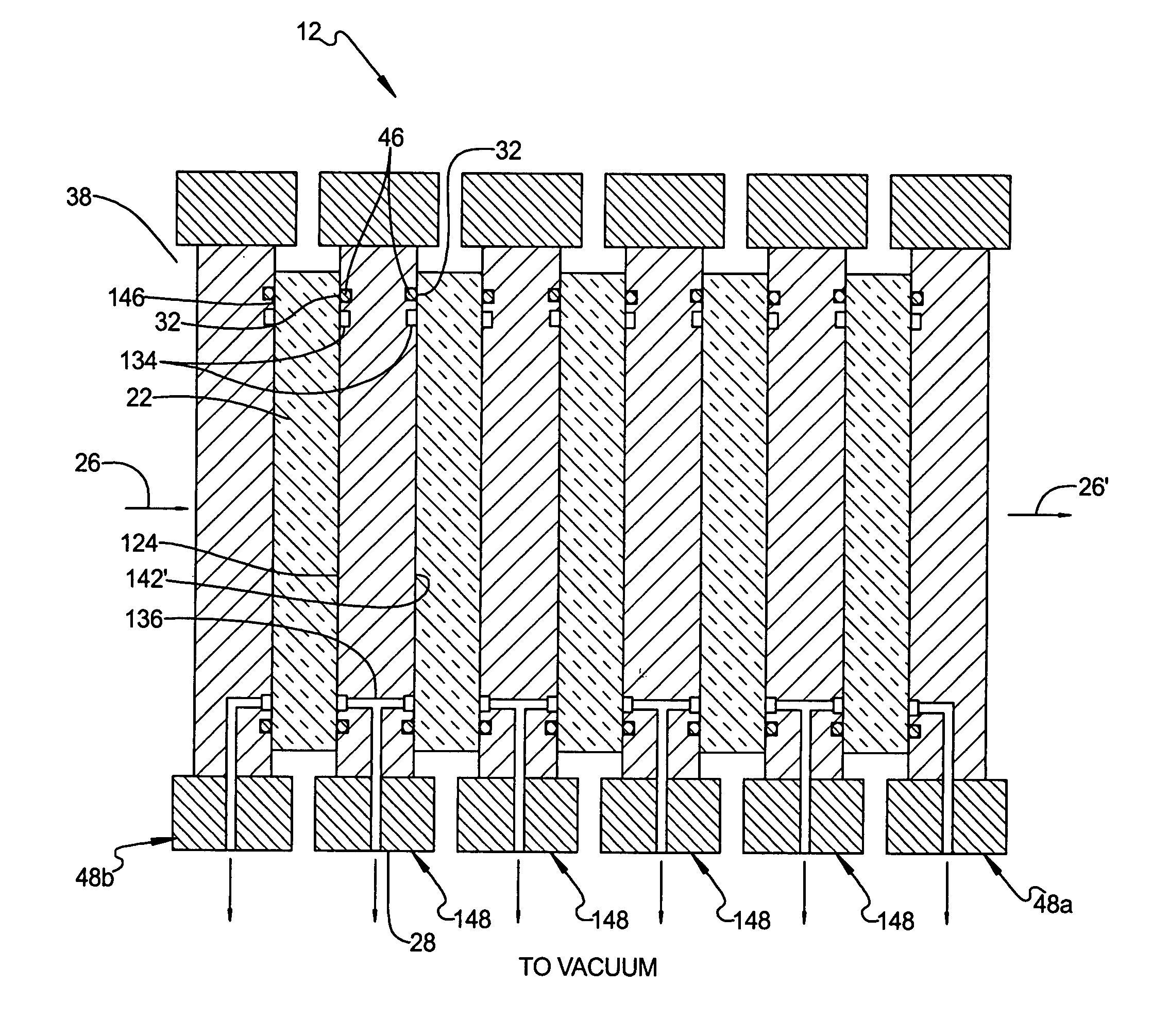
[0029] Referring to FIGS. 3a and 3b, there is shown a cooled optical assembly 10 in accordance with a first preferred embodiment of the present invention comprising a transparent optical component (TOC) 22 and a heat sink assembly 48. The cooled optical assembly 10 receives an incident laser beam 26 and transmits it therethrough to form a laser beam 26′. The heat sink assembly 48 further comprises an optically transparent heat conductor (THC) 24 and a heat sink 28. The TOC 22 is a flat ...


PUM


Abstract

A cooling system for use in with a transmissive optical element of a high average power laser (HAP). The system includes at least one optically transmissive element (TOC) that is held by a differential pressure in thermal contact with a heat sink assembly. In one embodiment, the heat sink assembly includes an optically transparent heat conductor (THC) attached to at least one face of the TOC. A vacuum formed between adjacent faces of the TOC and THC urges the facing planar surfaces into thermal contact with one another. Waste heat generated in the TOC is conducted to the THC. The temperature gradient inside the TOC is maintained substantially parallel to the direction of a laser beam being directed through the THC so that a given phase front of the beam exposes TOC material to the same temperature. As a result, the TOC does not perturb the phase front of the laser beam.

Description

FIELD OF THE INVENTION [0001] The present invention relates generally to cooling techniques for optical elements employed in laser systems, and more particularly, to conductive face-cooled optical elements for use in optical systems which are required to process / handle the output of High Average Power (HAP) laser systems. BACKGROUND OF THE INVENTION [0002] Overview [0003] Transmissive optical components used in high-average power (HAP) lasers experience significant heat load due to absorption of optical energy and other processes. This heat must be removed (often in real time) for the transmissive optical component to operate correctly and efficiently. For example, the process of frequency conversion in a nonlinear laser material generates heat within the nonlinear material medium due to absorption. This heat must be removed if the frequency converter is to operate efficiently at a significant power level. Also, the process of storing energy in a solid state laser amplifier material...

Claims


Application Information

Patent Timeline
Patent Type & Authority Applications(United States)
IPC IPC(8): H01S3/10
CPCG02F1/0102G02F1/3501G02F2203/60H01S3/0401H01S3/0405H01S3/0407H01S3/042H01S3/07
Inventor VETROVEC, JANELLIOTT, WILLIAM C.
Owner THE BOEING CO
Why Eureka
Try Eureka