
Exhaust gas purification system

a technology of exhaust gas purification system and filter, which is applied in the direction of physical/chemical process catalysts, metal/metal-oxide/metal-hydroxide catalysts, and separation processes. it can solve the problems of reducing fuel economy, small amount of heat from hc combustion supplied to the catalyst to the filter, and low flow rate of exhaust gas in the downstream oxidation catalyst. , to achieve the effect of quick regenerating the filter and preventing an increase in fuel consumption

Inactive Publication Date: 2006-03-23
MAZDA MOTOR CORP
View PDF5 Cites 25 Cited by
  • Summary
  • Abstract
  • Description
  • Claims
  • Application Information

AI Technical Summary

Benefits of technology

[0009] An object of the present invention is to allow the catalyst upstream of the filter to effectively work for the heating of the filter, i.e., for the burning-off of particulates, based on a different viewpoint from the cell density and thus solve the problem of HC slipping through the catalyst and in turn the problem of decrease in fuel economy.
[0015] In contrast, in the present invention, since upstream part of the catalyst has a small amount of support material, it has a small heat capacity and therefore is likely to raise its temperature, which is advantageous to early activation. Through the early activation of the catalyst, exhaust gas is promptly raised in temperature by heat of HC combustion at the upstream part of the catalyst. When the exhaust gas raised in temperature reaches downstream part of the catalyst, the downstream part rapidly activates the oxidation reactions of HC because of a large amount of support material. Therefore, the rate of increase in exhaust gas temperature rapidly goes up as compared to the above case where the support material is distributed uniformly. Specifically, active oxygen is released from the oxygen storage component which is a support material contained in the catalyst. Heat of combustion is produced in the process of the released active oxygen oxidizing CO in exhaust gas to CO2. Under the influence of the heat of combustion, the oxidation of HC in exhaust gas by the action of the catalytic metal is activated to produce a large amount of heat of HC combustion. In this manner, since downstream part of the catalyst has a larger amount of support material than upstream part thereof, the temperature of exhaust gas flowing into the filter can be raised without the above problem that HC slips through the catalyst. Further, even if a large amount of heat is dissipated to the outside in the course of passage of exhaust gas through the catalyst or in the course of movement of exhaust gas from the catalyst to the filter, a decrease in the temperature of exhaust gas flowing into the filter can be lessened.
[0016] Accordingly, even when post injection is carried out, the amount of fuel injected can be reduced. Further, even when thermal energy is additionally applied to the catalyst for the purpose of promoting its activity, the amount of energy added can be reduced. In these respects, the exhaust gas purification system of the present invention is advantageous in quickly regenerating the filter while preventing an increase in fuel consumption.
[0022] As described above, in the exhaust gas purification system of the present invention, the oxidation catalyst for oxidizing HC in exhaust gas, which is disposed upstream of the particulate filter in an exhaust passage, has a structure that part of the catalyst downstream in the direction of flow of exhaust gas has a larger amount of support material than upstream part thereof. Therefore, the exhaust gas temperature at the filter entrance can be increased as compared to the case where the support material is distributed uniformly over the entire length of the catalyst along the direction of flow of exhaust gas. This is advantageous in quickly regenerating the filter while preventing an increase in fuel consumption.

Problems solved by technology

Since, however, the flow rate of exhaust gas in the downstream oxidation catalyst is low, increase in HC in the exhaust gas produces a large amount of oxidation reaction heat of HC so that the downstream catalyst becomes likely to reach the necessary temperature for burning off soot.
Since in this case HC flows into the filter without being burned off by the oxidation catalyst, this means the amount of heat of HC combustion supplied from the catalyst to the filter is small, which is disadvantageous in the ignition of particulates deposited on the filter.
In turn, this means that the amount of fuel supplied to the oxidation catalyst for the purpose of filter regeneration (i.e., the amount of post-injected fuel) is increased, leading to decreased fuel economy.
Further, if unburned HC slipping through the oxidation catalyst is stored in the filter, it ignites to cause excessive temperature rise of the filter due to abnormal burning during burning-off of particulates, which is causes of deterioration of the catalytic metal supported on the filter and melting loss and cracks of the filter body.

Method used


Image

  • Exhaust gas purification system
  • Exhaust gas purification system

Examples


example 2

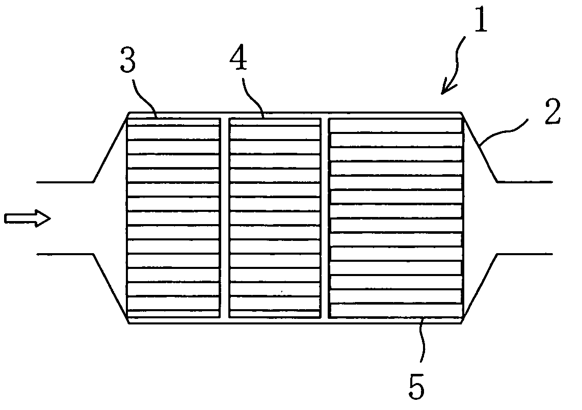
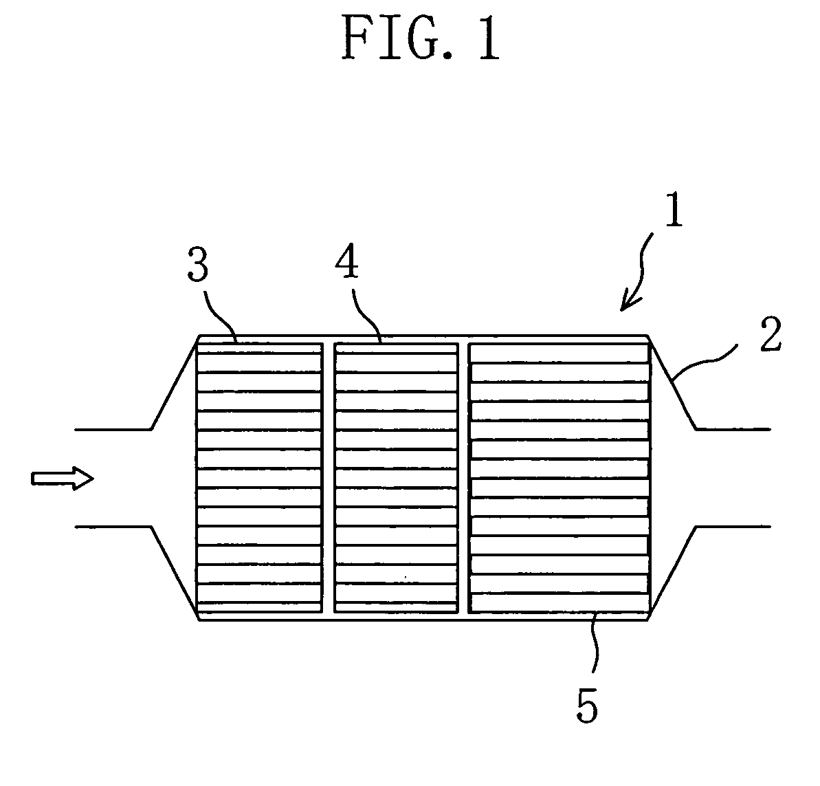
[0035] Both the upstream catalyst 3 and the downstream catalyst 4 are lean-NOx catalysts. The catalytic material is made of active alumina, CeO2, barium (Ba) serving as a NOx storage component and platinum (Pt) serving as a catalytic metal. Each catalyst was made by mixing active alumina and CeO2 in a mass ratio of 1:1 to prepare a support material and supporting Pt and Ba on the support material. As a support for each of the upstream and downstream catalysts 3 and 4 was used a cordierite honeycomb support of the same type as in Example 1.

[0036] Further, for the upstream catalyst 3, the support material obtained by mixing active alumina and CeO2 in a mass ratio of 1:1 was supported by 60 g / L on the honeycomb support. For the downstream catalyst 4, the same support material was supported by 180 g / L on the honeycomb support. Therefore, the downstream catalyst 4 contains a larger amount of support material per unit area of wall surfaces of each cell in the honeycomb support than the u...


PUM

PropertyMeasurementUnit
Temperatureaaaaaaaaaa

Abstract

An upstream catalyst (3) and a downstream catalyst (4) are disposed upstream of a particulate filter (5) in an exhaust passage of a diesel engine. The downstream catalyst (4) has a larger amount of support material for supporting catalytic metal than the upstream catalyst (3). This enhances the efficiency of oxidation reactions of HC in the catalysts to raise the temperature of exhaust gas flowing into the filter (5).

Description

CROSS-REFERENCES TO RELATED APPLICATIONS [0001] This application claims priority under 35 USC 119 to Japanese Patent Application No. 2004-275480, filed on Sep. 22, 2004, the entire contents of which are incorporated herein by reference. BACKGROUND OF THE INVENTION [0002] (a) Field of the Invention [0003] This invention relates to an exhaust gas purification system for a diesel engine. [0004] (b) Description of the Related Art [0005] Exhaust gas purification systems for diesel engines are generally known in which a filter for trapping particulates in exhaust gas is disposed in an exhaust passage and an oxidation catalyst is disposed upstream of the filter in the exhaust passage. These exhaust gas purification systems use reaction heat in the oxidation catalyst to raise the temperature of the filter up to a temperature at which particulates ignite and burn in order to regenerate the filter. The regeneration of the filter is implemented, for example, by increasing the amount of hydroca...

Claims


Application Information

Patent Timeline
IPC IPC(8): F01N3/00F01N3/10
CPCB01D53/9422Y02T10/22B01D53/9477B01D2251/208B01D2255/1021B01D2255/2042B01D2255/206B01D2255/407B01D2255/50B01D2255/908B01D2255/91B01D2255/912B01D2255/915B01J23/63B01J35/0006B01J37/0215B01J37/0242B01J37/0246B01D53/9454Y02T10/12B01J35/19
Inventor HARADA, KOICHIROTSUSHIO, YOSHINORITAKAMI, AKIHIDE
Owner MAZDA MOTOR CORP
Learn More