
Exhaust gas purifying apparatus and method of regenerating the same

a technology of exhaust gas purification and purification chamber, which is applied in the direction of machines/engines, domestic applications, chemical/physical processes, etc., can solve the problems of easy cracking when thermal shock is caused by exhaust gas from an internal combustion engine on board a construction machine, harmful to the environment and human body, etc., to achieve excellent catalyst activity and thermal diffusion, smooth absorbing and releasing, and excellent thermal shock resistance

Inactive Publication Date: 2006-03-23
IBIDEN CO LTD
View PDF16 Cites 73 Cited by
  • Summary
  • Abstract
  • Description
  • Claims
  • Application Information

AI Technical Summary

Benefits of technology

[0025] More specifically, according to the present invention, the electric resistance and thermal conductivity of the honeycomb structure are very much improved by increasing the crystallinity of the silicon so that the half-width of silicon peak (2θ=about 28°), observed by the X-ray diffraction, of the honeycomb structure will be 0.6° or less. It is considered that as the result, the electric properties of the honeycomb structure will be improved and regeneration of the honeycomb structure be improved by the catalyst. In addition, the thermal diffusion of the honeycomb structure is also improved. Even if a temperature distribution takes place in the honeycomb structure or a heat cycle has been repeated, the honeycomb structure will store less thermal stress and thus have a higher thermal shock resistance.
[0057] As having been described in the foregoing, in the exhaust gas purifying apparatus according to the present invention, the honeycomb structure is formed from the composite material comprising ceramic particles and crystalline silicon to capture particulates in exhaust gas, and the particulates are heated at a temperature of 250 to 800° C. by the filter regenerating means including a heating means such as a heater or the like provided in the exhaust gas purifying apparatus or by the heat of the exhaust gas itself without using the filter regenerating means. Thus, the honeycomb structure is excellent in catalyst activity and thermal diffusion, and in thermal shock resistance as well because the thermal stress will not easily be stored even after a temperature distribution takes place and heat cycle is repeated.

Problems solved by technology

Recently, it has been pointed out that the particulates in exhaust gas from an internal combustion engine on board in a vehicle such as a bus, truck or the like and a construction machine are harmful to the environment and human body.
Indeed, the honeycomb filter made from the silicon carbide is advantageous in that it has high thermal conductivity, while being not advantageous in that it is easy to crack when thermally shocked.
However, in case the honeycomb structure formed from a composite material comprising silicon carbide and metallic silicon is used as a filter in an exhaust gas purifying apparatus, repetition of particulate capture and filter regeneration will lead to gradual increase of pressure loss.

Method used


Image

  • Exhaust gas purifying apparatus and method of regenerating the same
  • Exhaust gas purifying apparatus and method of regenerating the same
  • Exhaust gas purifying apparatus and method of regenerating the same

Examples


example 1

[0205] (1) A crude paste was prepared by wet blending of 80 percent by mass of α-type silicon carbide powder of 30 μm in mean particle size and 20 percent by mass of crystalline silicon powder (whose half-width of silicon peak (2θ=about 28°) observed by the X-ray diffraction is 0.6°) of 4 μm in mean particle size to provide a powder mixture, and then adding 6 parts by weight of an organic binder (methyl cellulose), 2.5 parts by weight of a surface active agent (oleic acid) and 24 parts by weight of water to 100 parts by weight of the powder mixture.

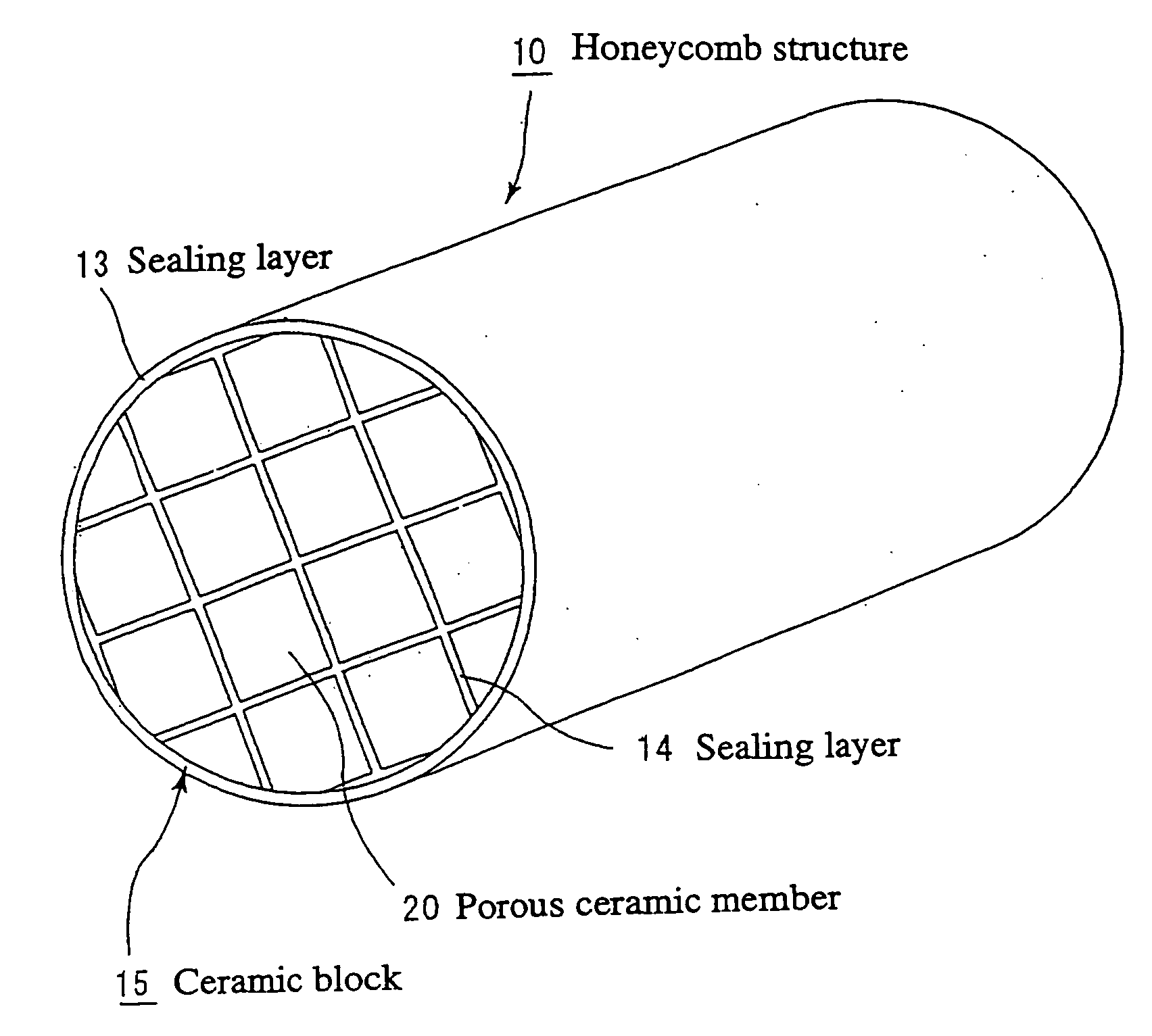
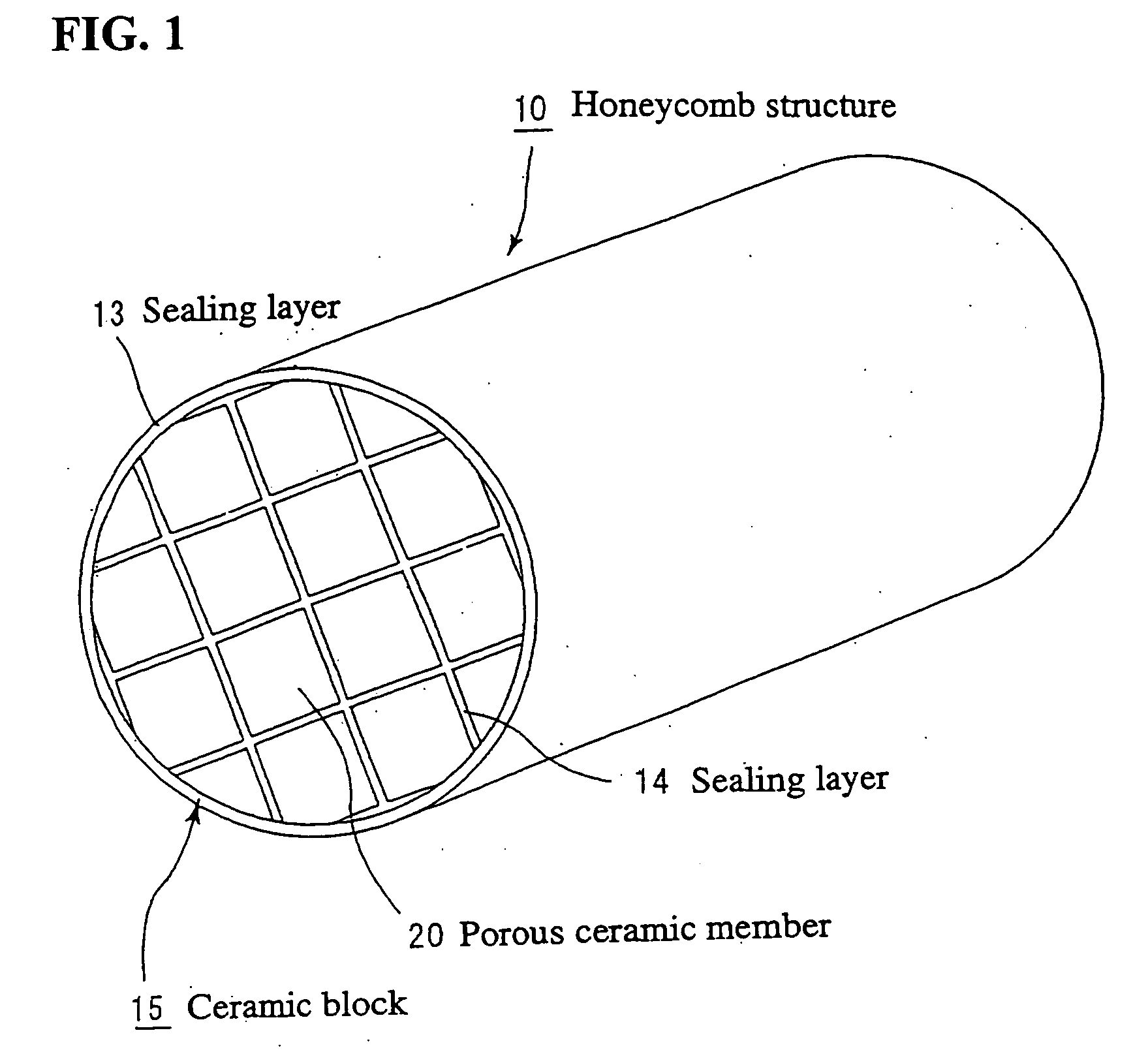
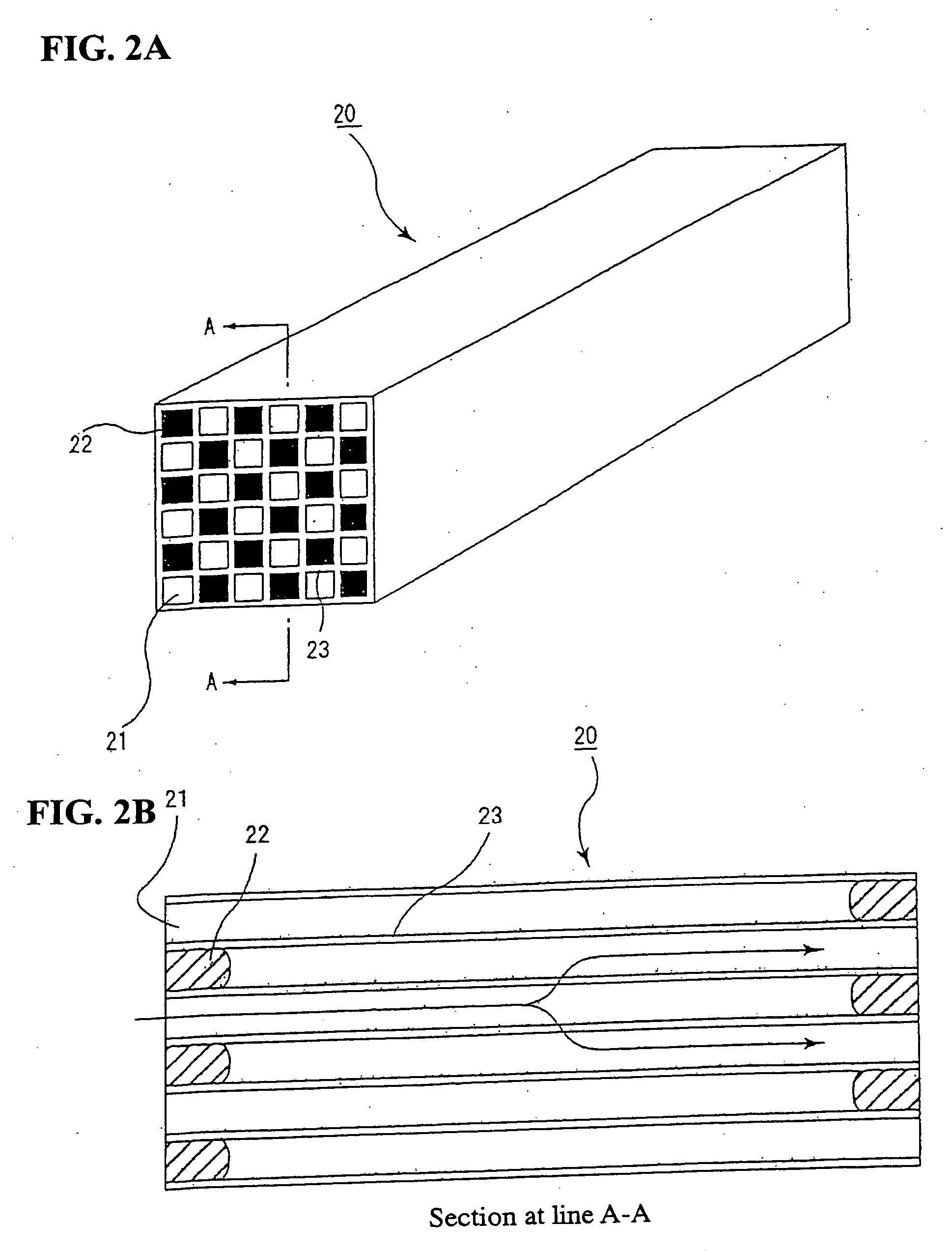
[0206] Next, the crude paste was put in an extrusion molding machine and formed at an extrusion rate of 10 cm / min into a green molding having the generally same shape as the porous ceramic member 20 shown in FIG. 2.

[0207] The green molding was dried by a microwave dryer to provide a dry ceramic molding. Then, a paste-like sealing material having the similar composition to that of the green molding was filled into ends of selected cells....

example 2

[0214] (1) A porous ceramic member was prepared as in the step (1) for preparation of the above Example 1 except that after bonding the silicon carbide particles together by the single crystal silicon, the baking was made at 2,200° C. for 2 hours.

[0215] (2) A honeycomb structure was formed using the above porous ceramic members together as in the step (2) for preparation of the Example 1, and the exhaust gas purifying apparatus as shown in FIG. 4 was built using the honeycomb structure as a filter (Sample 2).

example 3

[0216] (1) A porous ceramic member was prepared as in the step (1) for preparation of the above Example 1 except that after bonding the silicon carbide particles together by the single crystal silicon, the baking was made at 2,200° C. for 3 hours.

[0217] (2) A honeycomb structure was formed using the above porous ceramic members together as in the step (2) for preparation of the Example 1, and the exhaust gas purifying apparatus as shown in FIG. 4 was built using the honeycomb structure as a filter (Sample 3).


PUM

PropertyMeasurementUnit
Temperatureaaaaaaaaaa
Angleaaaaaaaaaa

Abstract

An exhaust gas purifying apparatus is provided which includes a honeycomb structure used as a filter to capture particulates in exhaust gas from an internal combustion engine such as diesel engine and as a carrier of a catalyst to convert the exhaust gas. The honeycomb structure is formed from a composite material comprising ceramic particles and crystalline silicon. The particulates captured by the honeycomb structure are removed by combustion at a temperature of 250 to 800° C., thereby, even if a relatively low temperature is distributed or a heat cycle has been repeated from a long term, thermal stress is prevented from being stored, cracking is prevented and thermal shock resistance is thus improved.

Description

FIELD OF THE INVENTION [0001] The present invention relates to an exhaust gas purifying apparatus using a honeycomb structure as a filter to capture particulates in exhaust gas from an internal combustion engine such as a diesel engine or as a support of a catalyst to convert the exhaust gas, and a method of regenerating the exhaust gas purifying apparatus by removing, by burning, the particulates etc. captured by the honeycomb structure. BACKGROUND ART [0002] Recently, it has been pointed out that the particulates in exhaust gas from an internal combustion engine on board in a vehicle such as a bus, truck or the like and a construction machine are harmful to the environment and human body. [0003] It has been proposed to use an exhaust gas purifying apparatus using porous ceramics, namely, a ceramic filter, as a device to capture and remove particulates in exhaust gas. [0004] As a typical ceramic filter, there is well known, for example, a ceramic honeycomb filter including a plural...

Claims


Application Information

Patent Timeline
IPC IPC(8): B01D46/00B01D46/24B01D53/94B01J21/08B01J27/224B01J35/04C04B35/117C04B35/565C04B38/00F01N3/022F01N3/28F02B3/06F02B37/00F02M25/07
CPCB01D46/0063Y02T10/22B01D46/2444B01D53/944B01D53/9445B01D2255/102B01J21/08B01J27/224B01J35/04C04B35/117C04B35/565C04B35/62655C04B38/0006C04B2111/0081C04B2235/383C04B2235/428C04B2235/5436C04B2235/5445C04B2235/5472C04B2235/6567C04B2235/77C04B2235/80F01N3/0222F01N3/2892F01N2450/28F02B3/06F02B37/00F02B2275/14F02M25/0707F02M25/0731B01D46/2418Y02T10/20C04B22/02F02M26/05F02M26/28Y02T10/12B01D46/84B01D46/2476B01J35/56F01N3/022F01N3/28F01N3/02F01N3/023
Inventor YOSHIDA, YUTAKA
Owner IBIDEN CO LTD
Learn More