
Method of increasing deposition rate of silicon dioxide on a catalyst

Active Publication Date: 2006-03-02
MICRON TECH INC
View PDF55 Cites 399 Cited by
  • Summary
  • Abstract
  • Description
  • Claims
  • Application Information

AI Technical Summary

Benefits of technology

[0010] The invention is useful in forming silicon dioxide layers over features that have flat surfaces to features such as contact openings and trenches having a high aspect ratio of up to about 20-30:1 and higher, providing good step coverage over the sidewalls and base of the feature at a low deposition temperature. The higher deposition rate of the silicon dioxide results in a higher throughput and increased production output. The invention provides a useful process for forming nanofilms that are useful in applications such as fiber electronics, among others. In addition, the porous aluminum oxide (Al2O3) layer has a lower k value than dense Al2O3, which is useful in IMD applications where lower parasitic capacitance is desirable.

Problems solved by technology

However, the rate of deposition of silicon dioxide to fill a trench or other opening using an ALD process is less than desirable.

Method used


Image

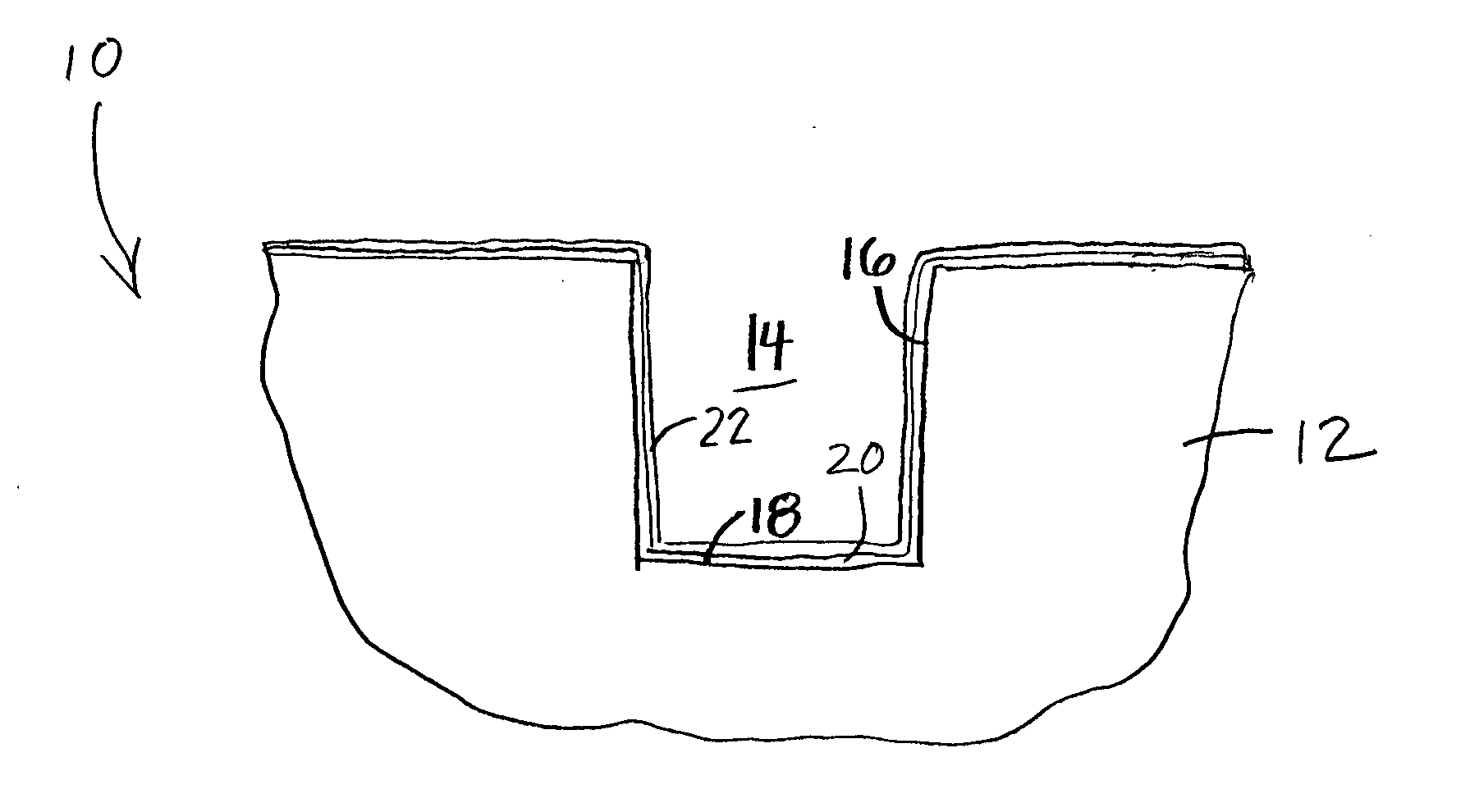
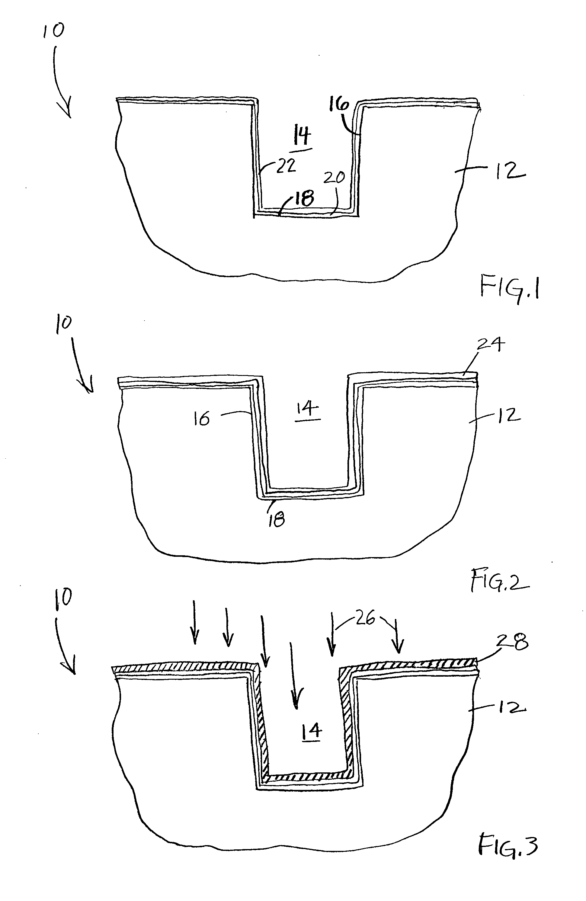
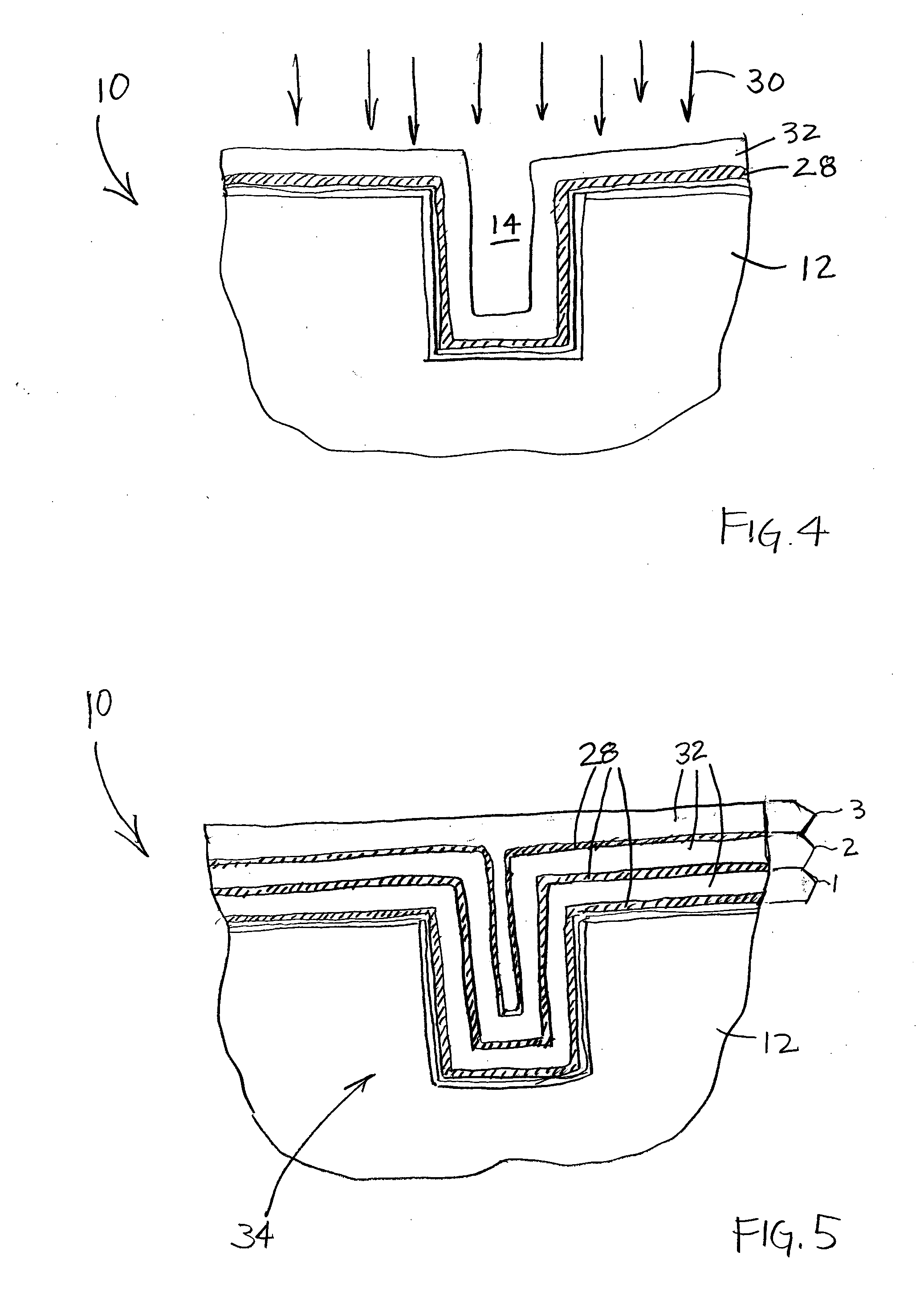
  • Method of increasing deposition rate of silicon dioxide on a catalyst
  • Method of increasing deposition rate of silicon dioxide on a catalyst
  • Method of increasing deposition rate of silicon dioxide on a catalyst

Examples


Embodiment Construction

[0015] The invention will be described generally with reference to the drawings for the purpose of illustrating the present preferred embodiments only and not for purposes of limiting the same. The figures illustrate processing steps for use in the fabrication of semiconductor devices in accordance with the present invention. It should be readily apparent that the processing steps are only a portion of the entire fabrication process.

[0016] In the context of the current application, the term “semiconductor substrate” or “semiconductive substrate” or “semiconductive wafer fragment” or “wafer fragment” or “wafer” will be understood to mean any construction comprising semiconductor material, including but not limited to bulk semiconductive materials such as a semiconductor wafer (either alone or in assemblies comprising other materials thereon), and semiconductive material layers (either alone or in assemblies comprising other materials). The term “substrate” refers to any supporting s...


PUM

PropertyMeasurementUnit
Temperatureaaaaaaaaaa
Timeaaaaaaaaaa
Timeaaaaaaaaaa

Abstract

Methods for forming dielectric layers, and structures and devices resulting from such methods, and systems that incorporate the devices are provided. The invention provides an aluminum oxide / silicon oxide laminate film formed by sequentially exposing a substrate to an organoaluminum catalyst to form a monolayer over the surface, remote plasmas of oxygen and nitrogen to convert the organoaluminum layer to a porous aluminum oxide layer, and a silanol precursor to form a thick layer of silicon dioxide over the porous oxide layer. The process provides an increased rate of deposition of the silicon dioxide, with each cycle producing a thick layer of silicon dioxide of about 120 Å over the layer of porous aluminum oxide.

Description

FIELD OF THE INVENTION [0001] The invention relates generally to semiconductor processing methods of forming dielectric fill materials, and more particularly to methods of forming silicon dioxide layers on substrates using a catalyst. BACKGROUND OF THE INVENTION [0002] Insulative materials are widely used in semiconductor fabrication methods for forming structures to electrically isolate the various active components formed in integrated circuits. Devices that extend into a semiconductive substrate can be electrically isolated by insulative materials formed within the substrate between the components, for example, trench isolation regions. In such a technique, trenches are etched into a silicon substrate, usually by anisotropic etching, and the trenches are subsequently filled by the deposition of an oxide such as silicon dioxide (SiO2). [0003] Due to the reduction in component size, microelectronic devices now require processing methods for forming nanosized components and accompan...

Claims


Application Information

Patent Timeline
IPC IPC(8): H01L21/31
CPCC23C16/403C23C16/45525C23C16/45534H01L21/02164H01L21/02178H01L21/022H01L21/31695H01L21/02216H01L21/02274H01L21/0228H01L21/316H01L21/31683H01L21/02203
Inventor HILL, CHRIS W.DERDERIAN, GARO J.
Owner MICRON TECH INC
Learn More