Carbon monoxide adsorption for carbon monoxide clean-up in a fuel cell system

a fuel cell and carbon monoxide technology, applied in the direction of physical/chemical process catalysts, other chemical processes, separation processes, etc., can solve the problems of consumption of hydrogen, and high cost of catalysts, so as to reduce carbon monoxide content, reduce hydrogen consumption, and eliminate the effect of us

Inactive Publication Date: 2006-02-16
GM GLOBAL TECH OPERATIONS LLC
View PDF23 Cites 5 Cited by
  • Summary
  • Abstract
  • Description
  • Claims
  • Application Information

AI Technical Summary

Benefits of technology

[0009] The present invention advantageously eliminates the use of a preferential oxidation (PROX) reactor, by providing an apparatus which incorporates CO adsorption in the place of the PROX reactor. The present invention provides a means to reduce carbon monoxide content while minimizing hydrogen consumption and the concomitant, undesirable excess low grade heat generation. The present invention reduces start-up duration, and improves overall fuel processor thermal efficiency during normal operation.

Problems solved by technology

The catalytic particles are typically costly precious metal particles.
These membrane electrode assemblies are relatively expensive to manufacture and require certain conditions for effective operation.
However, such fuels must be dissociated to release the hydrogen content thereof for fueling the fuel cell.
Unfortunately, the preferential oxidation reactor is not 100% selective and results in consumption of hydrogen.
The heat generated from the preferential oxidation reactor is at a low temperature, resulting in excess low-grade heat.
The operational gasoline fuel processor technologies to date do not meet automotive targets for start-up durations, mass, and volume.
The start-up time for such a system is limited by the time delay until the combination of water gas shift and preferential oxidation reactors can supply stack grade hydrogen.
Another limitation of the current technology is the inability to utilize the low grade heat such a system generates.
Any heat loss reduces the fuel processor thermal efficiency.

Method used


Image

  • Carbon monoxide adsorption for carbon monoxide clean-up in a fuel cell system
  • Carbon monoxide adsorption for carbon monoxide clean-up in a fuel cell system
  • Carbon monoxide adsorption for carbon monoxide clean-up in a fuel cell system

Examples


Embodiment Construction

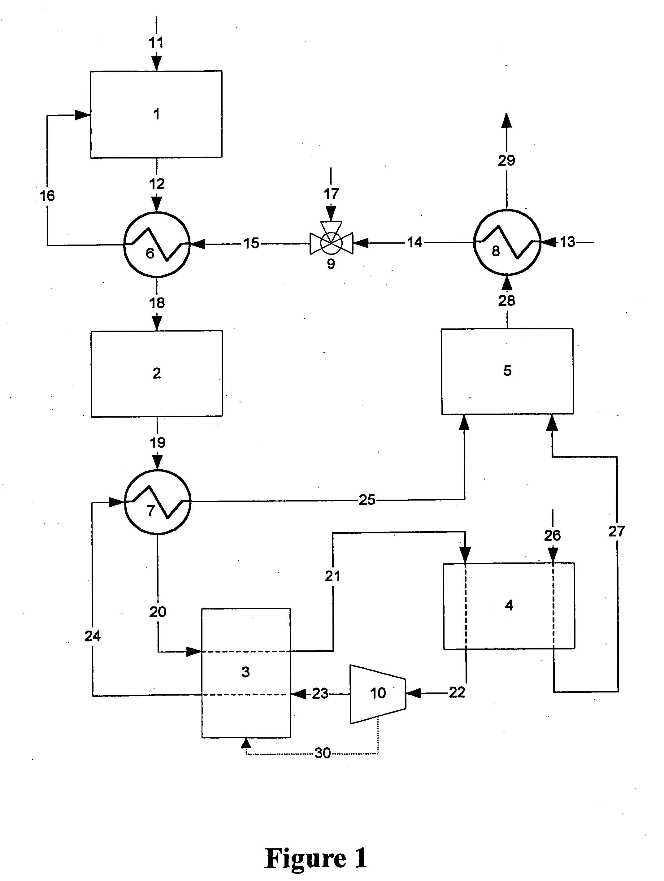
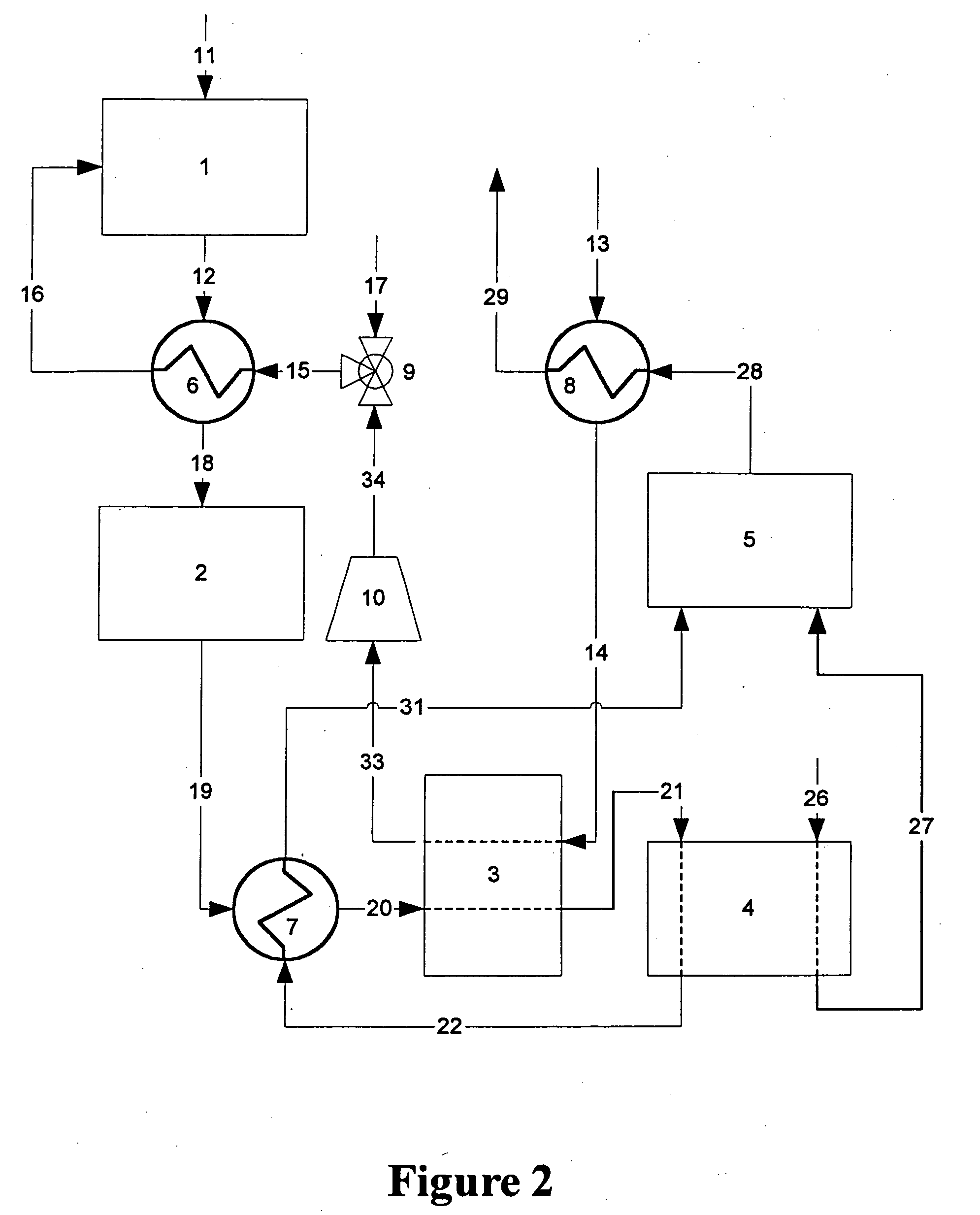
[0014] Flow diagrams of a preferred and alternate embodiment for a fuel processor system for a fuel cell vehicle using an adsorber as the primary means for carbon monoxide cleanup are shown in FIGS. 1 and 2, respectively.

[0015] Referring now to FIG. 1, hydrocarbon fuel such as, for example, gasoline, natural gas, methane, propane, methanol, ethanol, and / or mixtures thereof, etc. is fed into the fuel cell engine through stream 11. The fuel is fed into primary reactor 1 where it reacts with the steam / air mixture entering reactor 1 though stream 16. The steam is generated in heat exchanger 8, where liquid water from stream 13 is heated and vaporized by the hot exhaust stream 28 coming from combustor 5. The steam exits heat exchanger 8 in stream 14 and is blended with compressed air stream 17 in mixing valve 9. The steam / air mixture stream 15 is further heated in heat exchanger 6 to form hot steam / air mixture stream 16 for feed into primary reactor 1. The heat required to raise the tem...


PUM

PropertyMeasurementUnit
temperatureaaaaaaaaaa
operating temperatureaaaaaaaaaa

Abstract

An apparatus removes carbon monoxide (CO) from a hydrogen-rich gas stream in a hydrogen fuel cell system. CO fouls costly catalytic particles in the membrane electrode assemblies of proton exchange membrane (PEM) fuel cells. A vessel houses a carbon monoxide adsorbent. The vessel may be a rotating pressure swing adsorber. A water gas shift reactor is upstream of the rotating pressure swing adsorber. The water gas shift reactor may include a second adsorbent adapted to adsorb carbon monoxide at low temperatures and to desorb carbon monoxide at high temperatures. The apparatus advantageously eliminates the use of a preferential oxidation (PROX) reactor, by providing an apparatus which incorporates CO adsorption in the place of the PROX reactor. This cleans up carbon monoxide without hydrogen consumption and the concomitant, undesirable excess low grade heat generation. The present invention reduces start-up duration, and improves overall fuel processor efficiency during normal operation.

Description

CROSS-REFERENCE TO RELATED APPLICATIONS [0001] This application is a divisional of U.S. patent application Ser. No. 09 / 780,184 filed on Feb. 9, 2001. The disclosure of the above application is incorporated herein by reference.FIELD OF THE INVENTION [0002] The present invention relates generally to a fuel processor for a hydrogen fuel cell engine, and more specifically to such a processor which uses carbon monoxide (CO) adsorption for CO clean-up. BACKGROUND OF THE INVENTION [0003] In proton exchange membrane (PEM) fuel cells, hydrogen (H2) is the anode reactant (i.e. fuel) and oxygen is the cathode reactant (i.e. oxidant). The oxygen can be either a pure form (O2), or air (a mixture of O2 and N2). The solid polymer electrolytes are typically made from ion exchange resins such as perfluoronated sulfonic acid. The anode / cathode typically comprises finely divided catalytic particles, which are often supported on carbon particles, and mixed with a proton conductive resin. The catalytic ...

Claims


Application Information

Patent Timeline
Patent Type & Authority Applications(United States)
IPC IPC(8): C01B3/24B01D53/04B01D53/047B01D53/06B01J20/18B01J20/20C01B3/38C01B3/48C01B3/56H01M8/06H01M8/10
CPCB01D53/047Y02E60/50B01D53/261B01D2253/102B01D2253/104B01D2253/106B01D2253/108B01D2253/1124B01D2253/25B01D2256/16B01D2257/502B01D2257/80B01D2258/0208B01D2259/40001B01D2259/40052B01D2259/40056B01D2259/40081B01D2259/4145C01B3/48C01B3/56C01B2203/0283C01B2203/043C01B2203/0465C01B2203/047C01B2203/0475C01B2203/0495C01B2203/066C01B2203/146H01M8/0662B01D53/06
Inventor GITTLEMAN, CRAIG S.PETTIT, WILLIAM H.VOECKS, GERALD E.
Owner GM GLOBAL TECH OPERATIONS LLC
Why Eureka
Try Eureka