
Clustered enterprise JavaTM in a secure distributed processing system

a distributed processing system and enterprise javatm technology, applied in the field of distributed processing systems, can solve the problems of difficult maintenance of application code on clients, inability to meet the requirements of distributed processing system fault tolerance, etc., to achieve efficient load balancing and session concentration, improve the effect of fault tolerance of distributed processing system, and efficient scalability

Inactive Publication Date: 2006-02-09
ORACLE INT CORP
View PDF56 Cites 28 Cited by
  • Summary
  • Abstract
  • Description
  • Claims
  • Application Information

AI Technical Summary

Benefits of technology

The present invention provides a distributed processing system with improved fault tolerance and scalability. The system includes a communication medium and two processing devices. The first processing device emulates a processing device called a Java virtual machine (JVM) and has a data structure called a remote Java virtual machine (RJVM). The second processing device has a similar data structure called a RJVM. The system also includes software programs for load balancing, session concentration, message forwarding, and failover. The system can be used in a variety of programming models and supports industry standards. The load balancing software program can select service providers based on various criteria such as load, data type, time period, and affinity for service providers. The system can be used in a peer-to-peer network and includes a stub for load balancing and failover. The system also includes an application program coded in a stateless program model for efficient scalability.

Problems solved by technology

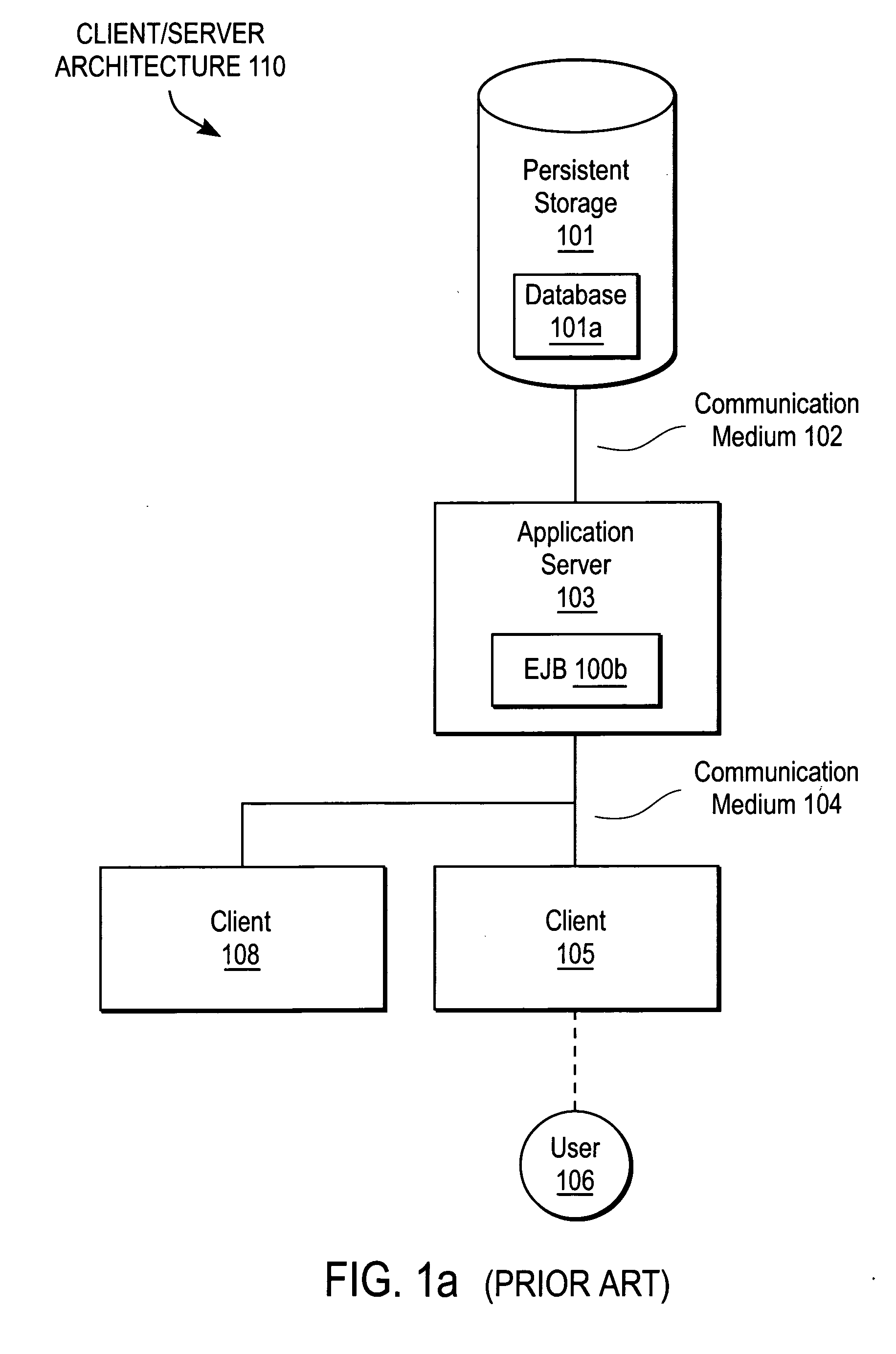
First, architecture 110 does not scale well because server 103 has to handle many connections.
In addition, adding twice as many processing devices (clients) does not necessarily provide you with twice as much performance.
Second, it is difficult to maintain application code on clients 105 and 108.
Third, architecture 110 is susceptible to system failures or a single point of failure.
If server 101 fails and a backup is not available, client 105 will not be able to obtain the service.
First, a failure of a single processing device or TP monitor 224 may render the network inoperable.
Second, the scalability or number of processing devices (both servers and clients) coupled to TP monitor 224 may be limited by TP monitor 224 hardware and software.
Third, flexibility in routing a client request to a server is limited.
Fourth, a client typically does not know the state of a back-end server or other processing device.
Fifth, no industry standard software or APIs are used for load balancing.
And sixth, a client typically may not select a particular server even if the client has relevant information which would enable efficient service.

Method used


Image

  • Clustered enterprise JavaTM in a secure distributed processing system
  • Clustered enterprise JavaTM in a secure distributed processing system
  • Clustered enterprise JavaTM in a secure distributed processing system

Examples


Embodiment Construction

I. Clustered Enterprise Java™ Distributed Processing System

[0076] A. Clustered Enterprise Java™ Software Architecture

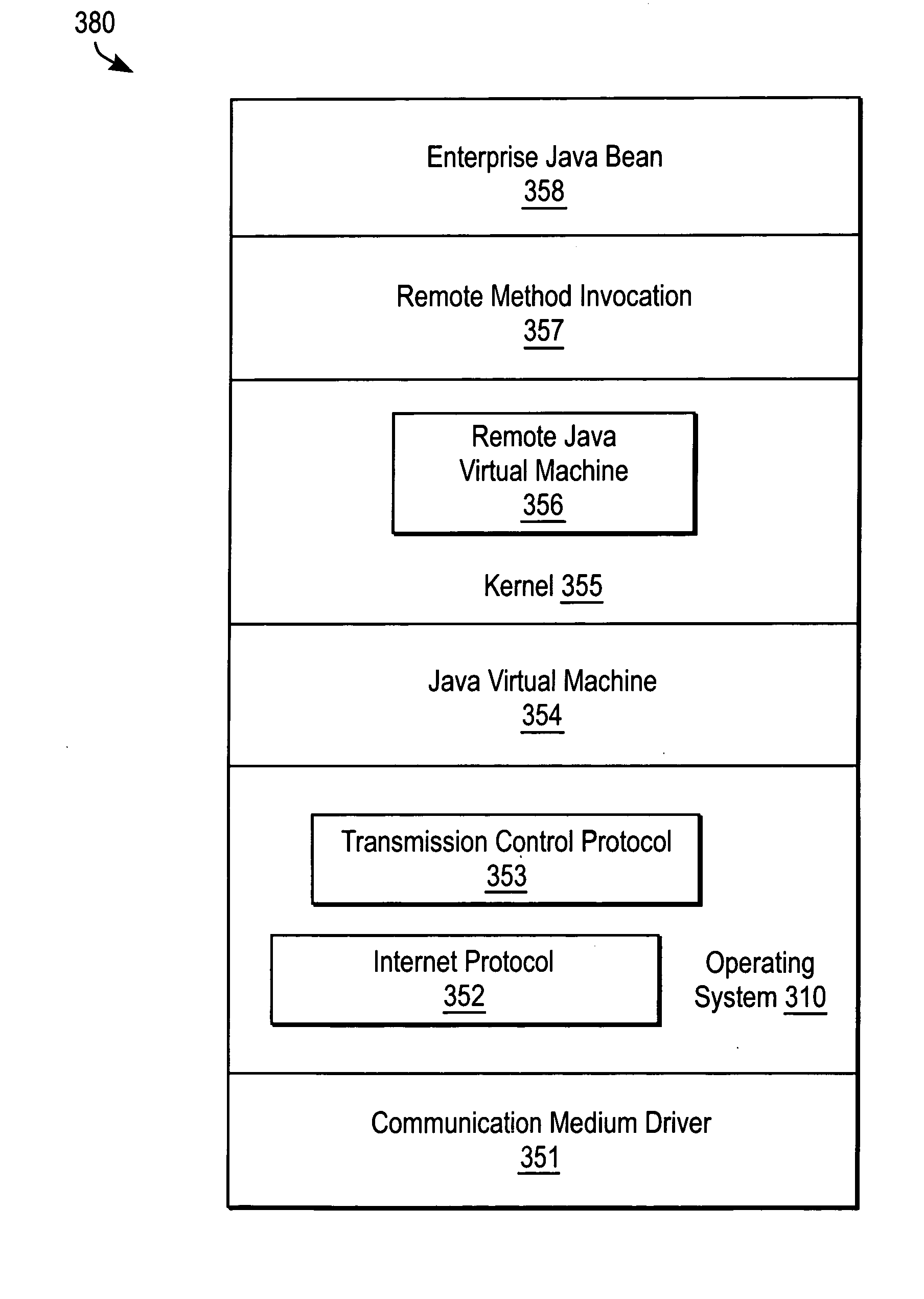
[0077]FIG. 3a illustrates a simplified block diagram 380 of the software layers in a processing device of a clustered enterprise Java™ system, according to an embodiment of the present invention. A detailed description of a clustered enterprise Java™ distributed processing system is described below. The first layer of software includes a communication medium software driver 351 for transferring and receiving information on a communication medium, such as an ethernet local area network. An operating system 310 including a transmission control protocol (“TCP”) software component 353 and internet protocol (“IP”) software component 352 are upper software layers for retrieving and sending packages or blocks of information in a particular format. An “upper” software layer is generally defined as a software component which utilizes or accesses one or more “lower” software l...


PUM


Abstract

A clustered enterprise distributed processing system. The distributed processing system includes a first and a second computer coupled to a communication medium. The first computer includes a virtual machine (JVM) and kernel software layer for transferring messages, including a remote virtual machine (RJVM). The second computer includes a JVM and a kernel software layer having a RJVM. Messages are passed from a RJVM to the JVM in one computer to the JVM and RJVM in the second computer. Messages may be forwarded through an intermediate server or rerouted after a network reconfiguration. Each computer includes a smart stub having a replica handler, including a load balancing software component and a failover software component. Each computer includes a duplicated service naming tree for storing a pool of smart stubs at a node.

Description

CLAIM OF PRIORITY [0001] This application is a continuation of application Ser. No. 10 / 427,798, filed May 1, 2003, which is a continuation of application Ser. No. 09 / 405,500, filed Sep. 23, 1999, which claims the benefit of U.S. Provisional Application No. 60 / 107,167, filed Nov. 5, 1998, all of which are incorporated herein by reference.CROSS REFERENCE TO RELATED APPLICATIONS [0002] The following copending U.S. patent applications are assigned to the assignee of the present application, and their disclosures are incorporated herein by reference: [0003] (A) Ser. No. 09 / 405,318 filed Sep. 23, 1999 by Dean B. Jacobs and Anno R. Langen entitled “CLUSTERED ENTERPRISE JAVA™ HAVING A MESSAGE PASSING KERNEL IN A DISTRIBUTED PROCESSING SYSTEM”, now U.S. Pat. No. 6,385,643 issued May 7, 2002; [0004] (B) Ser. No. 09 / 405,260 filed Sep. 23, 1999 by Dean B. Jacobs and Eric M. Halpern entitled “SMART STUB OR ENTERPRISE JAVA™ BEAN IN A DISTRIBUTED PROCESSING SYSTEM”; [0005] (C) Ser. No. 09 / 405,508 ...

Claims


Application Information

Patent Timeline
Patent Type & Authority Applications(United States)
IPC IPC(8): G06F9/46G06F13/00G06F15/16
CPCG06F9/465G06F9/548G06F9/546G06F9/544G06F15/16
Inventor JACOBS, DEAN B.LANGEN, ANNO R.
Owner ORACLE INT CORP
Learn More